Drive modules
188
3.
DRIVE MODULES
Mo
dula
r d
riv
es
130
DDS
HARDWARE
Ref.1310
X3 connector
This connector of the modular drive offers two possible configurations:
Encoder simulator
Direct feedback
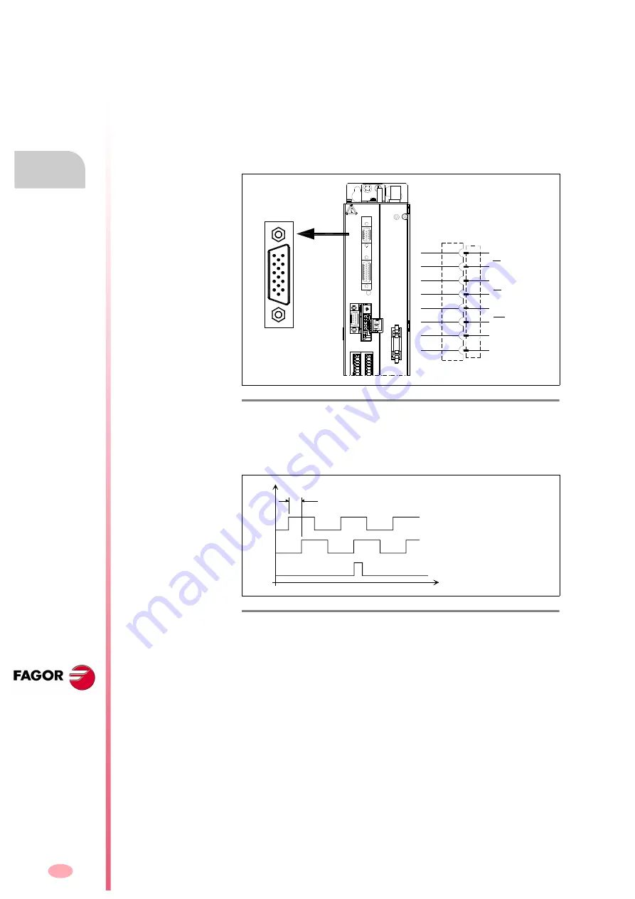
X3. Encoder simulator
Having installed the encoder simulator card, X3 is a high density (HD) 15-
pin sub-D type male (M) connector whose pins are galvanically isolated
from the rest of the drive.
It outputs square differential TTL pulses simulating those of an encoder
that would be mounted on the motor shaft.
The number of pulses per turn and the position of the reference mark I0
are programmable.
F. H3/62
Connector X3. Pinout.
F. H3/63
Connector X3. Pulses per revolution and reference mark position.
15
14
13
12
11
10
9
8
7
6
1
2
3
4
5
A
A
I0
I0
GND
B
B
CHASSIS
2
1
3
4
5
6
11
15
DRI
VE M
O
DULE
X4
X3
X1
STATUS
DISPLAY
X5
X6
SL2
SL1
90° PHASE-SHIFT
V
A
I
0
V
B
t
V
OH
> 2.5 V
V
OL
< 0.5 V
I
SURCE
< 20 mA
I
SINK
< 20 mA
Summary of Contents for DDS
Page 1: ...DRIVE DDS Hardware manual Ref 1310...
Page 6: ...I 6 DDS HARDWARE Ref 1310...
Page 9: ......
Page 10: ......
Page 11: ......
Page 12: ......
Page 16: ...16 Ref 1310 DDS HARDWARE...
Page 30: ...1 DESCRIPTION 30 Description DDS HARDWARE Ref 1310...
Page 94: ...2 POWER SUPPLIES 94 Power supplies DDS HARDWARE Ref 1310...
Page 188: ...3 DRIVE MODULES 188 Drive modules DDS HARDWARE Ref 1310...
Page 204: ...4 AUXILIARY MODULES 204 Auxiliary modules DDS HARDWARE Ref 1310...
Page 232: ...SELECTING CRITERIA 5 232 Selection criteria DDS HARDWARE Ref 1310...
Page 266: ...7 CABLES 266 Cables DDS HARDWARE Ref 1310...
Page 312: ...8 INSTALLATION 312 Installation DDS HARDWARE Ref 1310...
Page 326: ...9 FUNCTIONAL SAFETY 326 Functional safety DDS HARDWARE Ref 1310...
Page 354: ...10 CONNECTION DIAGRAMS 354 Connection diagrams DDS HARDWARE Ref 1310...
Page 378: ...12 SALES REFERENCES 378 Sales references DDS HARDWARE Ref 1310...
Page 384: ...13 COMPATIBILITY 384 Compatibility DDS HARDWARE Ref 1310...
Page 385: ......

