Auxiliary modules
AUXILIARY MODULES
Chokes
4.
191
DDS
HARDWARE
Ref.1310
4.2 Chokes
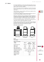
The chokes (inductances or coils) are used with regenerative power sup-
plies (XPS-25 and XPS-65) and regenerative regulated power supplies
(RPS-80, RPS-75, RPS-45 and RPS-20).
When returning power to mains, the impedance of mains for the outgoing
currents is very low. Hence, the up ramps of this current must be limited
with a choke.
These three-phase chokes for XPS and RPS power supplies must be
connected to the power line input.
On the XPS power supplies, the choke must be connected to power ter-
minals CH1 and CH2 located at the bottom of the module.
RPS power supplies do not have connection terminals at the bottom of
the module like at XPS power supplies; therefore, it must be connected to
the power line between the MAINS FILTER
A and the RPS power
supply itself. See diagrams in the corresponding chapter of this manual.
The internal switching mechanism of these power supplies generates a
regenerative current to mains already filtered by this choke.
FAGOR provides the XPS-25 and XPS-65-A chokes that must necessarily
go with the corresponding XPS power supplies and the RPS-75-3, RPS-45
and RPS-20 chokes that must go with RPS power supplies.
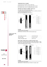
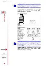
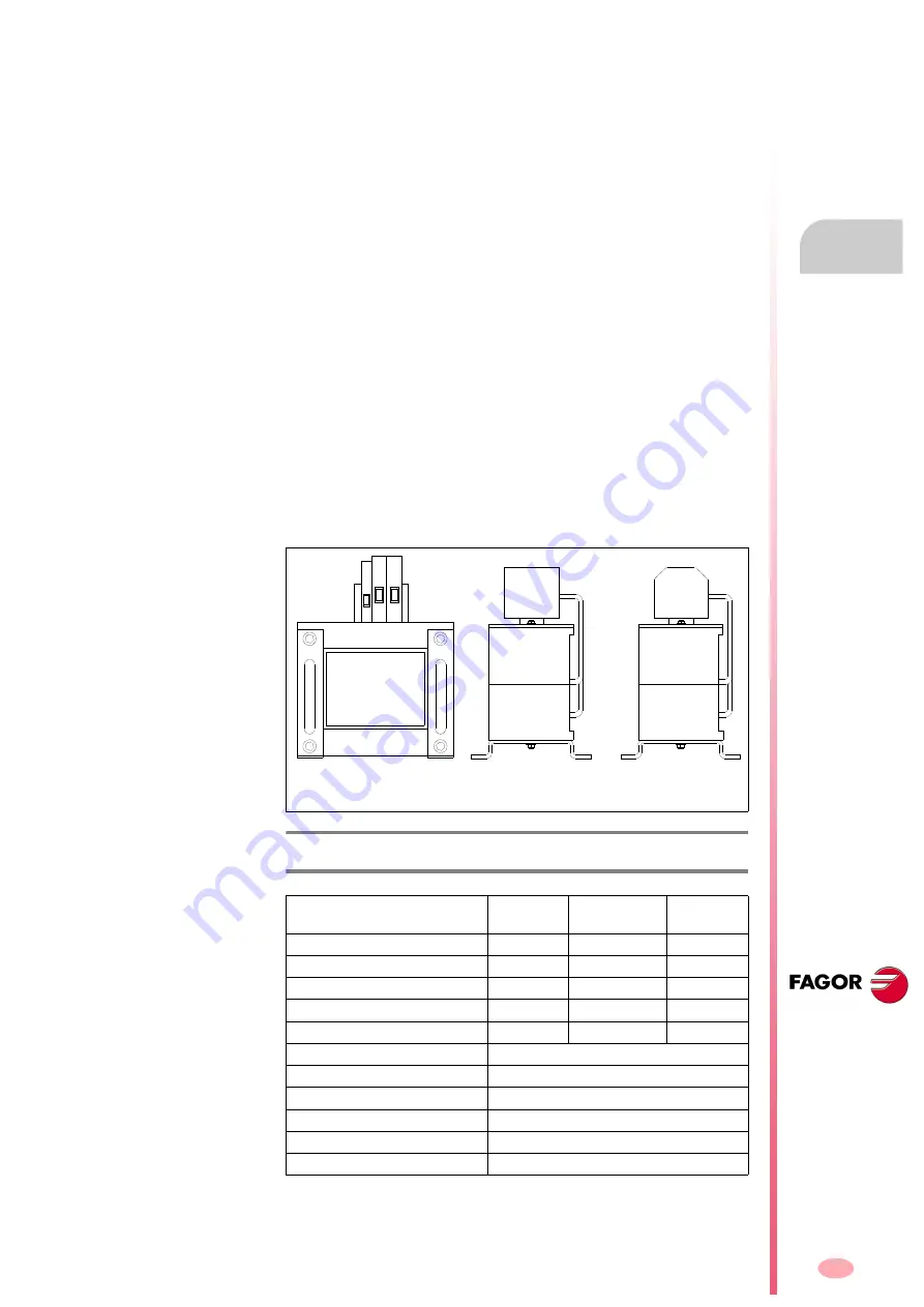
XPS chokes. Technical data
F. H4/2
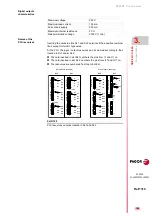
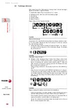
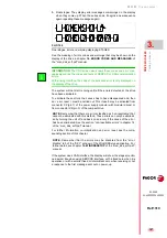
XPS CHOKES.
T. H4/3
Technical data.
CHOKE
XPS-25
XPS-65
DISCONTINUED
XPS-65-A
NEW
Inductance (10 kHz)
0.350 mH
0.175 mH
0.250 mH
Rated current
50 A
120 A
120 A
Peak current
100 A
180 A
185 A
Max. terminal section
10 mm²
50 mm²
70 mm²
Approximate mass kg (lb)
8.0 (17.6)
22.5 (49.3)
36.0 (79.3)
Operating amb.temperature
5°C to 45°C (41°F to 113°F)
Storage temperature
- 20°C to + 60°C (- 4°F to 140°F)
Relative humidity
80 % max.
Operating vibration
0.5 G
Shipping vibration
2 G
Sealing
IP 20
XPS-25 CHOKE
XPS-65 CHOKE
Discontinued
XPS-65-A CHOKE
New
Summary of Contents for DDS
Page 1: ...DRIVE DDS Hardware manual Ref 1310...
Page 6: ...I 6 DDS HARDWARE Ref 1310...
Page 9: ......
Page 10: ......
Page 11: ......
Page 12: ......
Page 16: ...16 Ref 1310 DDS HARDWARE...
Page 30: ...1 DESCRIPTION 30 Description DDS HARDWARE Ref 1310...
Page 94: ...2 POWER SUPPLIES 94 Power supplies DDS HARDWARE Ref 1310...
Page 188: ...3 DRIVE MODULES 188 Drive modules DDS HARDWARE Ref 1310...
Page 204: ...4 AUXILIARY MODULES 204 Auxiliary modules DDS HARDWARE Ref 1310...
Page 232: ...SELECTING CRITERIA 5 232 Selection criteria DDS HARDWARE Ref 1310...
Page 266: ...7 CABLES 266 Cables DDS HARDWARE Ref 1310...
Page 312: ...8 INSTALLATION 312 Installation DDS HARDWARE Ref 1310...
Page 326: ...9 FUNCTIONAL SAFETY 326 Functional safety DDS HARDWARE Ref 1310...
Page 354: ...10 CONNECTION DIAGRAMS 354 Connection diagrams DDS HARDWARE Ref 1310...
Page 378: ...12 SALES REFERENCES 378 Sales references DDS HARDWARE Ref 1310...
Page 384: ...13 COMPATIBILITY 384 Compatibility DDS HARDWARE Ref 1310...
Page 385: ......

