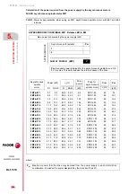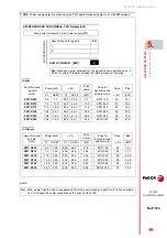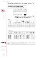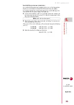
Selection criteria
S
E
LECT
ING CRI
T
ERIA
Asyn
ch
ronou
s
sp
indl
e mo
to
r an
d se
rvo
d
rive selectio
n
5.
215
DDS
HARDWARE
Ref.1310
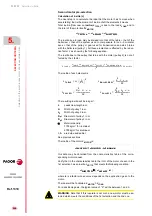
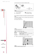
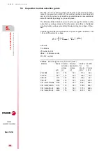
Limited acceleration and choke. Choke = (
acceleration /
t).
The capability demanded from the motor is determined by the following
formulas:
We will now give several examples of calculations using a mechanical
specifications and for a standard motor. The results could vary from real
ones through mechanical losses, fluctuations in mains voltage, or inaccu-
racies of mechanical data.
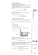
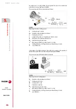
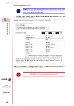
T. H5/3
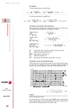
Different accelerations depending on speed.
Method
Different accelerations depending on speed
Control
Linear acceleration avoiding abrupt variations in
transmitted torque.
Comment
Emulation of the square sine function for speed by
using ramps.
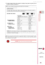
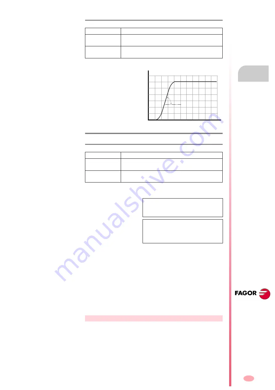
F. H5/10
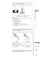
Acceleration and choke limit.
T. H5/4
Acceleration and choke limit.
Method
Acceleration and choke limit.
Control
Progressive linear acceleration, avoiding abrupt vari-
ations of transmitted torque.
Comment
Approach square sine function (bell shape) for the
speed.
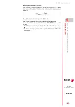
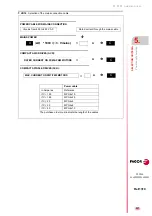
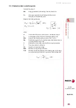
Capacity required by the motor
in the constant torque area:
(0 < N
M
< N
B
)
Capacity required by the motor
in the constant torque and con-
stant power area:
(0 < N
M
< N
max
)
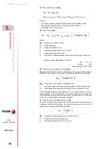
J
M
Inertia of the load in kg·m² as viewed from the motor shaft
P
N
Rated power at base speed kW
Nmax
Maximum motor speed in rev/min.
N
B
Motor base speed in rev/min.
N
M
Motor speed reached after a time period t in rpm
t
Acceleration time until N
M
(in seconds) is reached
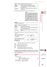
Example.
Data:
Acceleration time:
Between 0 and 1500 rpm in 0.5 s. (1)
Between 0 and 6000 rpm in 2.5 s. (2)
Motor inertia:
J
motor
= 0.13 kg·m²
Motor base speed:
N
b
= 1500 rev/min
adjust
time
0
speed
P
N
2
60
------
2
J
M
N
M
2
1000 t
--------------------
kW
=
P
N
2
60
------
2
J
M
N
M
2
N
B
2
+
2000 t
---------------------------------------
kW
=
Summary of Contents for DDS
Page 1: ...DRIVE DDS Hardware manual Ref 1310...
Page 6: ...I 6 DDS HARDWARE Ref 1310...
Page 9: ......
Page 10: ......
Page 11: ......
Page 12: ......
Page 16: ...16 Ref 1310 DDS HARDWARE...
Page 30: ...1 DESCRIPTION 30 Description DDS HARDWARE Ref 1310...
Page 94: ...2 POWER SUPPLIES 94 Power supplies DDS HARDWARE Ref 1310...
Page 188: ...3 DRIVE MODULES 188 Drive modules DDS HARDWARE Ref 1310...
Page 204: ...4 AUXILIARY MODULES 204 Auxiliary modules DDS HARDWARE Ref 1310...
Page 232: ...SELECTING CRITERIA 5 232 Selection criteria DDS HARDWARE Ref 1310...
Page 266: ...7 CABLES 266 Cables DDS HARDWARE Ref 1310...
Page 312: ...8 INSTALLATION 312 Installation DDS HARDWARE Ref 1310...
Page 326: ...9 FUNCTIONAL SAFETY 326 Functional safety DDS HARDWARE Ref 1310...
Page 354: ...10 CONNECTION DIAGRAMS 354 Connection diagrams DDS HARDWARE Ref 1310...
Page 378: ...12 SALES REFERENCES 378 Sales references DDS HARDWARE Ref 1310...
Page 384: ...13 COMPATIBILITY 384 Compatibility DDS HARDWARE Ref 1310...
Page 385: ......


