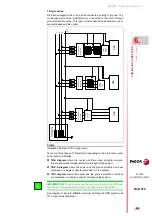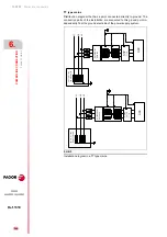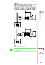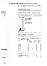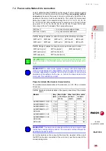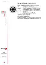
Power line connection
246
6.
POWER LINE CONNECTION
Prote
cti
on fu
ses
236
DDS
HARDWARE
Ref.1310
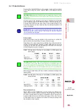
The fuse references given of the previous table are the ones that may be
installed to obtain the maximum power on each model. In those cases
where the power supply is oversized, the fuse value should be adjusted to
the actual requirements of the machine.
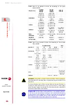
T. H6/3
Fuses to be installed in mains line depending on the power
supply installed.
Manufacturer
PS-25B4
XPS-25
RPS-20
PS-65A
XPS-65
RPS-45
RPS-75
RPS-80
BUSMANN
FWH45B
RF00-125A
-
XL50F-45A
XL50F-125A
-
RF-000-40A
RF-000-125A
-
40FE
100FE
160FE
170M2611
170M1318
170M1319
170M3009
170M3013
170M3014
GOULD
A00-66C5D8
A00-66C125D8
-
A00-66C5D1
A00-66C125D1
-
FERRAZ
6.9 gRB 00
D08L 040
6.9 gRB 00
D08L 125
6.9 gRB 00
D08L 160
6.6 gRB 000
D08/040
6.6 gRB 000
D08/100
6.6 gRB 000
D08/160
SIBA
20 189 20-50A
20 189 20-125A
20 189 20-160A
WICKMAN
45FEE
140FEE
-
SIEMENS
3NE8 003
3NE8 021
3NC8423-3
LITTELFUSE
-
L70S125
L70S150
T. H6/4
Fuses to be installed in mains line depending on the compact
drive installed.
ACD/SCD/CMC
SCD
MANUFACT.
1.08
1.15
1.25
2.35/50
2.75
BUSSMANN
FC-6A
FC-12A
FC-20A
FWC-32A10F
-
XL50-10A
XL50-15A
RF-000-25 FWP-32A14F
-
6CT
12CT
-
-
-
FWH-6.30A6F
-
-
-
-
GOULD
ST-6
10x38
ST-12
10x38
ST-20
10x38
-
-
000-10
000-16
A60x20
-
-
000/80-10
000/80-16
-
-
-
FERRAZ
6.600CP URC
14.51/6
12.600CP URC
14.51/6
-
-
6.921CP URQ
27x60/63
6.621CP URC
14.51/6
12.621CP URC
14.51/6
-
-
-
6.6URE10/6
12.6URE10/6
-
-
-
A60Q6-2
A60Q12-2
A60Q20-2
A60Q30-2
-
A60X6-1
A60X12-1
-
-
-
SIBA
-
-
-
-
50-140-34.63
without striker
-
-
-
-
50 142 34.63
with striker
SIEMENS
-
-
3NE8 015
3NE8 003
-
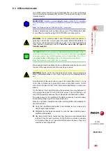
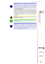
WARNING.
Using other protection devices instead of fuses (magneto-
thermal switches, for example) does no guarantee proper protection of the
equipment.
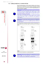
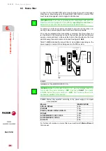
MANDATORY.
When using an autotransformer or an isolating transform-
er, the fuses must be selected according to its characteristics depending
on the structure of the installation. Therefore, the fuses must be selected
specifically for each installation since it will be affected by a variable num-
ber of characteristics internal and external to the machine.
Summary of Contents for DDS
Page 1: ...DRIVE DDS Hardware manual Ref 1310...
Page 6: ...I 6 DDS HARDWARE Ref 1310...
Page 9: ......
Page 10: ......
Page 11: ......
Page 12: ......
Page 16: ...16 Ref 1310 DDS HARDWARE...
Page 30: ...1 DESCRIPTION 30 Description DDS HARDWARE Ref 1310...
Page 94: ...2 POWER SUPPLIES 94 Power supplies DDS HARDWARE Ref 1310...
Page 188: ...3 DRIVE MODULES 188 Drive modules DDS HARDWARE Ref 1310...
Page 204: ...4 AUXILIARY MODULES 204 Auxiliary modules DDS HARDWARE Ref 1310...
Page 232: ...SELECTING CRITERIA 5 232 Selection criteria DDS HARDWARE Ref 1310...
Page 266: ...7 CABLES 266 Cables DDS HARDWARE Ref 1310...
Page 312: ...8 INSTALLATION 312 Installation DDS HARDWARE Ref 1310...
Page 326: ...9 FUNCTIONAL SAFETY 326 Functional safety DDS HARDWARE Ref 1310...
Page 354: ...10 CONNECTION DIAGRAMS 354 Connection diagrams DDS HARDWARE Ref 1310...
Page 378: ...12 SALES REFERENCES 378 Sales references DDS HARDWARE Ref 1310...
Page 384: ...13 COMPATIBILITY 384 Compatibility DDS HARDWARE Ref 1310...
Page 385: ......

