Power supplies
POWER SUPPLIES
Re
gen
erative pow
er
su
ppli
es
2.
55
DDS
HARDWARE
Ref.1310
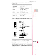
Lights indicating the status of the main power supply
The regenerative power supply XPS-25 has the following lights on the
front panel to indicate the status of the main power supply:
FAULT blinking.
The blinking red led indicates that
there are no er-
rors
and that
one or several mains phases are missing
.
FAULT turned ON.
The steady red led on indicates that there is an er-
ror. The error is indicated on the display of the drive modules.
FAULT turned OFF.
The led off indicates that there is no error and
that all mains phases are OK.
REGEN.
The led is lit when the module is working in energy regener-
ating mode.
DC BUS ON.
The green led indicates that the module is supplying all
its power at the bus.
Lights indicating the status of the auxiliary power supply
The regenerative power supply XPS-25 has the following lights on the
front panel to indicate the status of the integrated auxiliary power supply:
RESET.
Initializes the auxiliary 24 V DC power supply.
OVER VOLTAGE.
The red led indicates that there is an over-voltage
error at the 24 V DC output or due to over-temperature.
OVER CURRENT.
The red led indicates that there is an over-current
error at the 24 V DC output.
ON.
The green led it indicates that there are 24 V DC at the output.
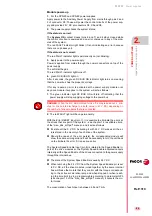
INFORMATION.
For further detail on these indicator lights, see the combi-
nation table for interpretation in the description of the E305 on the error list-
ing shown in chapter
14. ERROR CODES AND MESSAGES
of the
“man_dds_soft.pdf” manual.
i
Summary of Contents for DDS
Page 1: ...DRIVE DDS Hardware manual Ref 1310...
Page 6: ...I 6 DDS HARDWARE Ref 1310...
Page 9: ......
Page 10: ......
Page 11: ......
Page 12: ......
Page 16: ...16 Ref 1310 DDS HARDWARE...
Page 30: ...1 DESCRIPTION 30 Description DDS HARDWARE Ref 1310...
Page 94: ...2 POWER SUPPLIES 94 Power supplies DDS HARDWARE Ref 1310...
Page 188: ...3 DRIVE MODULES 188 Drive modules DDS HARDWARE Ref 1310...
Page 204: ...4 AUXILIARY MODULES 204 Auxiliary modules DDS HARDWARE Ref 1310...
Page 232: ...SELECTING CRITERIA 5 232 Selection criteria DDS HARDWARE Ref 1310...
Page 266: ...7 CABLES 266 Cables DDS HARDWARE Ref 1310...
Page 312: ...8 INSTALLATION 312 Installation DDS HARDWARE Ref 1310...
Page 326: ...9 FUNCTIONAL SAFETY 326 Functional safety DDS HARDWARE Ref 1310...
Page 354: ...10 CONNECTION DIAGRAMS 354 Connection diagrams DDS HARDWARE Ref 1310...
Page 378: ...12 SALES REFERENCES 378 Sales references DDS HARDWARE Ref 1310...
Page 384: ...13 COMPATIBILITY 384 Compatibility DDS HARDWARE Ref 1310...
Page 385: ......


