Power supplies
POWER SUPPLIES
Re
gene
rative regul
ated pow
er
su
ppli
es
2.
81
DDS
HARDWARE
Ref.1310
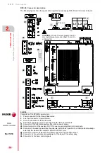
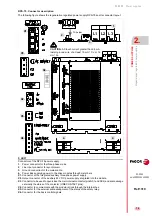
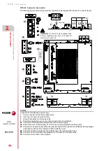
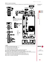
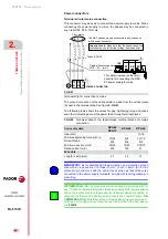
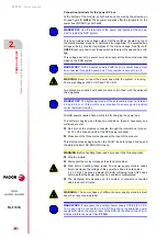
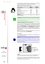
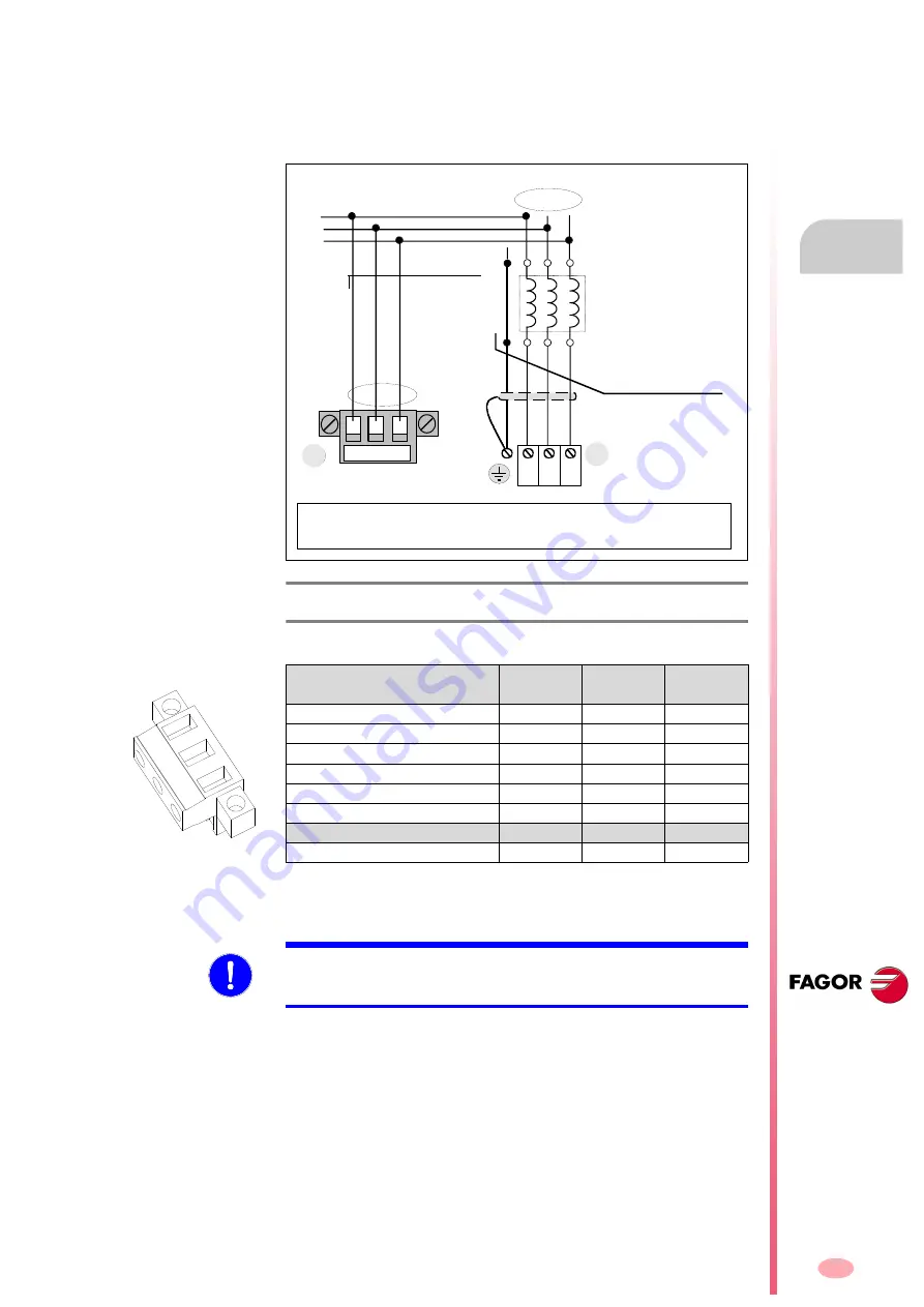
Terminal strip for connecting the mains voltage input
Three-phase line input taken at a point before the three single-phase RPS
chokes (one choke per phase). This connection is needed to receive the
mains line voltages and it is done through connector (2) as shown in the
next figure:
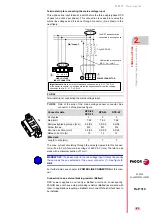
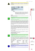
The max. current circulating through the wires (screwed into this connec-
tor) will be 8.5 mA for a mains voltage of 460 V AC (rms) Therefore, use
wires with a minimum section of 1 mm².
For further detail, see chapter
of this man-
ual.
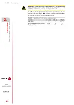
Connection to an external braking resistor (Ballast)
RPS power supplies do not carry a Ballast circuit and, consequently,
FAGOR does not have external braking resistors (Ballast) associated with
them. In applications requiring a Ballast circuit, one off-the-shelf will have to
be installed.
F. H2/42
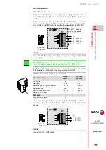
Terminal strip for connecting the mains voltage input.
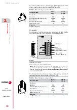
T. H2/30
Data of the pins of the mains voltage sensor connector. See
connector 2 of the previous figure.
Connector data
RPS-80
RPS-75
RPS-45
RPS-20
Nr of poles
3
3
3
Gap (mm)
7.62
7.62
7.62
Min/max tightening torque (N·m)
0.5/0.6
0.5/0.6
0.5/0.6
Screw thread
M3
M3
M3
Min./max. section (mm²)
0.2/2.5
0.2/2.5
0.2/2.5
Rated current In (A)
12
12
12
Wire data
Length to strip (mm)
7
7
7
1x
L3
L2
L1
The RST phases may be
connected in any sequence
LINE VOLTAGE
INPUT CONNECTOR
L 1 L2 L3
L3
L2
L1
From mains
S T
R
N
L1 L2 L3
2
)
Cable without connectors
MPC - 4x ... (mm
2
)
POWER CONNECTOR
Choke RPS-XX
u1 v1
w1
w2
v2
u2
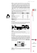
Important note:
Make sure that if the phase sequence is e.g. S-L1,T-L2,R-L3
at the power connector, it must then match the sequence set at the line voltage
connector; that is: S - L1, T-L2, R-L3 .
R
T
S
3x1 mm²
1.
2.
MANDATORY.
The phase order in the line voltage input (2) must be exactly
the same as the one selected at the power connector (1). See figure
Summary of Contents for DDS
Page 1: ...DRIVE DDS Hardware manual Ref 1310...
Page 6: ...I 6 DDS HARDWARE Ref 1310...
Page 9: ......
Page 10: ......
Page 11: ......
Page 12: ......
Page 16: ...16 Ref 1310 DDS HARDWARE...
Page 30: ...1 DESCRIPTION 30 Description DDS HARDWARE Ref 1310...
Page 94: ...2 POWER SUPPLIES 94 Power supplies DDS HARDWARE Ref 1310...
Page 188: ...3 DRIVE MODULES 188 Drive modules DDS HARDWARE Ref 1310...
Page 204: ...4 AUXILIARY MODULES 204 Auxiliary modules DDS HARDWARE Ref 1310...
Page 232: ...SELECTING CRITERIA 5 232 Selection criteria DDS HARDWARE Ref 1310...
Page 266: ...7 CABLES 266 Cables DDS HARDWARE Ref 1310...
Page 312: ...8 INSTALLATION 312 Installation DDS HARDWARE Ref 1310...
Page 326: ...9 FUNCTIONAL SAFETY 326 Functional safety DDS HARDWARE Ref 1310...
Page 354: ...10 CONNECTION DIAGRAMS 354 Connection diagrams DDS HARDWARE Ref 1310...
Page 378: ...12 SALES REFERENCES 378 Sales references DDS HARDWARE Ref 1310...
Page 384: ...13 COMPATIBILITY 384 Compatibility DDS HARDWARE Ref 1310...
Page 385: ......

