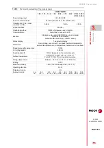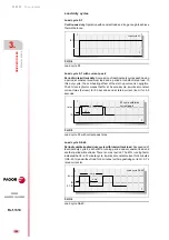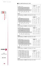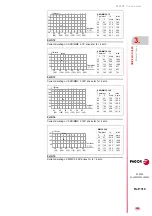
Power supplies
POWER SUPPLIES
Re
gene
rative regul
ated pow
er
su
ppli
es
2.
89
DDS
HARDWARE
Ref.1310
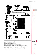
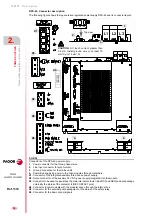
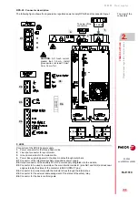
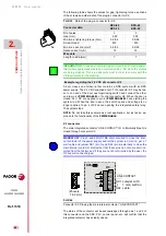
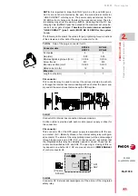
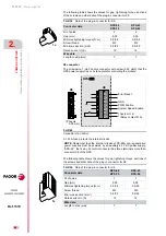
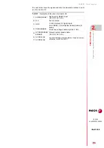
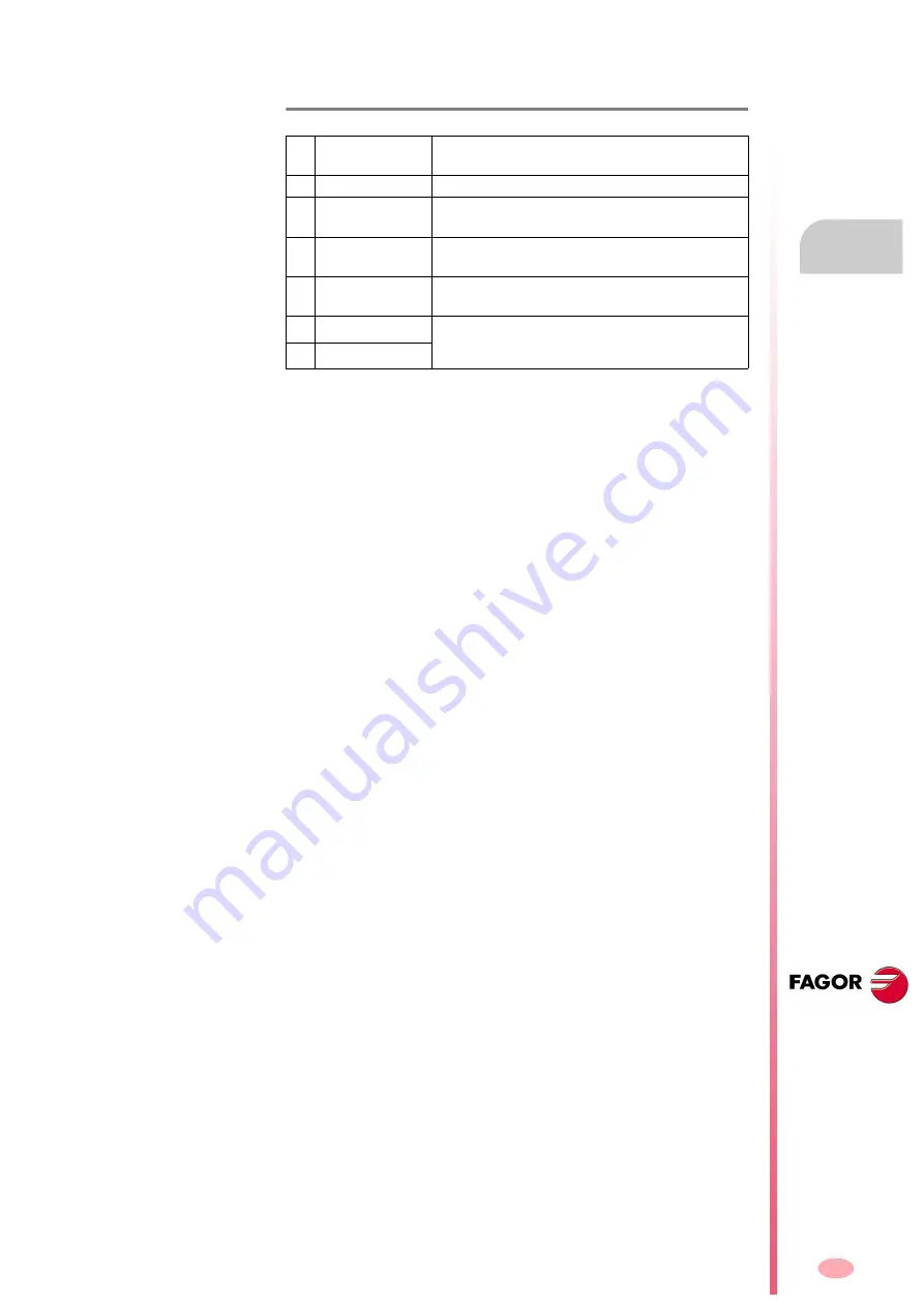
The next table shows the signals and other considerations related to each
pin of connector X6:
T. H2/37
Description of the pins of connector X6.
1
ERROR RESET
System error RESET input
(24 V DC; 4.5-7 mA).
2
N.C.
Not connected
3
GND
0 volts reference for digital inputs.
Error RESET (1) and System Speed Enable (5).
4
PWM ENABLE
Safety.
Power bus voltage enable input (24 V DC).
5
SYSTEM SPEED
ENABLE
General system speed enable.
(24 V DC; 4.5-7 mA).
6
SYSTEM OK
Contact indicating module status. It opens in case
of failure. Limit 1 A at 24 V.
7
SYSTEM OK
Summary of Contents for DDS
Page 1: ...DRIVE DDS Hardware manual Ref 1310...
Page 6: ...I 6 DDS HARDWARE Ref 1310...
Page 9: ......
Page 10: ......
Page 11: ......
Page 12: ......
Page 16: ...16 Ref 1310 DDS HARDWARE...
Page 30: ...1 DESCRIPTION 30 Description DDS HARDWARE Ref 1310...
Page 94: ...2 POWER SUPPLIES 94 Power supplies DDS HARDWARE Ref 1310...
Page 188: ...3 DRIVE MODULES 188 Drive modules DDS HARDWARE Ref 1310...
Page 204: ...4 AUXILIARY MODULES 204 Auxiliary modules DDS HARDWARE Ref 1310...
Page 232: ...SELECTING CRITERIA 5 232 Selection criteria DDS HARDWARE Ref 1310...
Page 266: ...7 CABLES 266 Cables DDS HARDWARE Ref 1310...
Page 312: ...8 INSTALLATION 312 Installation DDS HARDWARE Ref 1310...
Page 326: ...9 FUNCTIONAL SAFETY 326 Functional safety DDS HARDWARE Ref 1310...
Page 354: ...10 CONNECTION DIAGRAMS 354 Connection diagrams DDS HARDWARE Ref 1310...
Page 378: ...12 SALES REFERENCES 378 Sales references DDS HARDWARE Ref 1310...
Page 384: ...13 COMPATIBILITY 384 Compatibility DDS HARDWARE Ref 1310...
Page 385: ......

