Drive modules
188
3.
DRIVE MODULES
Mo
dula
r d
riv
es
98
DDS
HARDWARE
Ref.1310
Technical data
There are specific modular drives AXD to control synchronous motors (both for axis and spindle applica-
tions) and SPD to control asynchronous motors (in spindle applications). This chapter is common to
both models because their external characteristics (dimensions, connectors, ...) are the same.
Note that:
T. H3/1
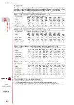
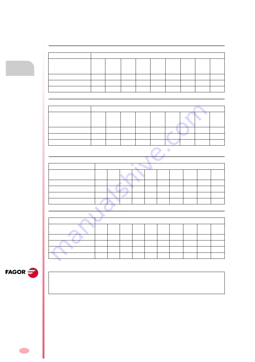
Currents on modular drives for synchronous motors. fc = 4 kHz.
With internal fan
Drive for synchronous motor (as axis)
Models
AXD
MMC
1.08
AXD
MMC
1.15
AXD
MMC
1.25
AXD
MMC
1.35
AXD
MMC
2.50
AXD
MMC
2.75
AXD
MMC
3.100
AXD
MMC
3.150
MMC
3.200
I S1= In Arms
4.0
7.5
12.5
17.5
25.0
37.5
50.0
75.0
90.0
Imax S1 Arms
8.0
15.0
25.0
35.0
50.0
75.0
100.0
150.0
180.0
Dissipated power W
33
69
88
156
225
270
351
536
834
T. H3/2
Currents on modular drives for synchronous motors. fc = 8 kHz.
With internal fan
Drive for synchronous motor (as axis)
Models
AXD
MMC
1.08
AXD
MMC
1.15
AXD
MMC
1.25
AXD
MMC
1.35
AXD
MMC
2.50
AXD
MMC
2.75
AXD
MMC
3.100
AXD
MMC
3.150
MMC
3.200
I S1= In Arms
4.0
7.5
12.5
17.5
25.0
37.5
50.0
75.0
90.0
Imax S1 Arms
8.0
15.0
25.0
35.0
50.0
75.0
100.0
150.0
180.0
Dissipated power W
44
89
132
195
305
389
510
605
840
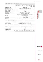
T. H3/3
Current in modular drives for synchronous or asynchronous motors. fc = 4 kHz.
With internal fan
Drive for synchronous or asynchronous motor (as spindle)
Models
SPD
1.15
SPD
1.25
SPD
1.35
SPD
2.50
SPD
2.75
SPD
2.85
SPD
3.100
SPD
3.150
SPD
3.200
SPD
3.250
I S1= In Arms
10.5
16.0
23.1
31.0
42.0
50.0
70.0
90.0 121.0 135.0
0.7 x In Arms
7.3
11.2
16.1
21.7
29.0
35.0
49.0
63.0
84.7
94.5
I S6-40 Arms
13.7
20.8
30.0
40.3
54.6
65.0
91.0
117.0 157.3 175.5
Dissipated power W
98
110
195
349
289
432
496
626
1163
1333
T. H3/4
Current in modular drives for synchronous or asynchronous motors. fc = 8 kHz.
With internal fan
Drive for synchronous or asynchronous motor (as spindle)
Models
SPD
1.15
SPD
1.25
SPD
1.35
SPD
2.50
SPD
2.75
SPD
2.85
SPD
3.100
SPD
3.150
SPD
3.200
SPD
3.250
I S1= In Arms
10.5
13.0
18.0
27.0
32.0
37.0
56.0
70.0
97.0 108.0
0.7 x In Arms
7.3
9.1
12.6
18.9
22.4
25.9
39.2
49.7
67.9
75.6
I S6-40 Arms
11.6
16.9
23.4
35.1
41.6
48.1
72.8
91.0 126.1 140.4
Dissipated power W
98
130
201
350
333
438
546
668
1187
1344
MMC drives have the same currents as AXD drives.
fc
. It represents the switching frequency of the IGBT's
The dissipated powers correspond to the operation at the rated current in S1 mode.
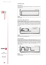
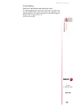
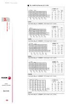
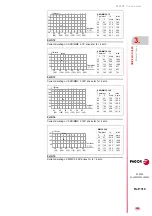
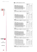
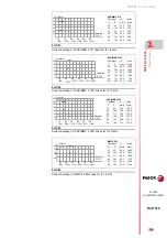
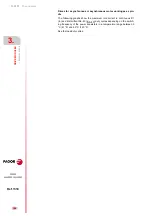
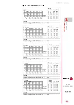
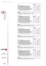
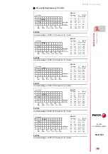
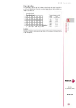
See the load duty cycle for the modular drives in the corresponding section of this chapter.
Summary of Contents for DDS
Page 1: ...DRIVE DDS Hardware manual Ref 1310...
Page 6: ...I 6 DDS HARDWARE Ref 1310...
Page 9: ......
Page 10: ......
Page 11: ......
Page 12: ......
Page 16: ...16 Ref 1310 DDS HARDWARE...
Page 30: ...1 DESCRIPTION 30 Description DDS HARDWARE Ref 1310...
Page 94: ...2 POWER SUPPLIES 94 Power supplies DDS HARDWARE Ref 1310...
Page 188: ...3 DRIVE MODULES 188 Drive modules DDS HARDWARE Ref 1310...
Page 204: ...4 AUXILIARY MODULES 204 Auxiliary modules DDS HARDWARE Ref 1310...
Page 232: ...SELECTING CRITERIA 5 232 Selection criteria DDS HARDWARE Ref 1310...
Page 266: ...7 CABLES 266 Cables DDS HARDWARE Ref 1310...
Page 312: ...8 INSTALLATION 312 Installation DDS HARDWARE Ref 1310...
Page 326: ...9 FUNCTIONAL SAFETY 326 Functional safety DDS HARDWARE Ref 1310...
Page 354: ...10 CONNECTION DIAGRAMS 354 Connection diagrams DDS HARDWARE Ref 1310...
Page 378: ...12 SALES REFERENCES 378 Sales references DDS HARDWARE Ref 1310...
Page 384: ...13 COMPATIBILITY 384 Compatibility DDS HARDWARE Ref 1310...
Page 385: ......

