background image

Operation Manual - Page: 13

NV-300T/301T Man: 9910 Soft: 2.xx

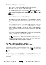
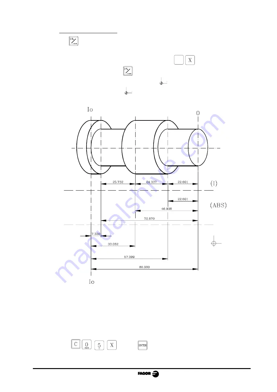
In absolute mode:

-

Press 

 until the ABS led comes on.

-

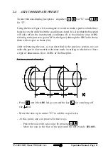
To preset part zero:

- Place the axis exactly over “0” and press: 

C


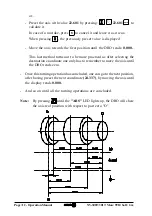
At any time, by pressing key 

 , the DRO will display the present position

with respect to the previous zero (ABS and 

 leds off), to part zero (ABS led

on) or with respect to home (

led on).

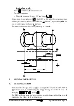
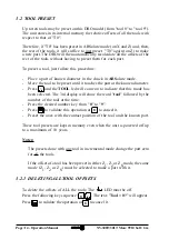
The next section describes how preset up to 10 tools.

3.

SPECIAL OPERATIONS

3.1

SCALING FACTOR

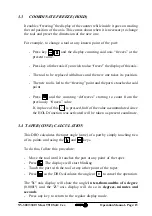
With this DRO, it is possible to apply a scaling factor between 0 and 9.999 for
applications such as mold making by simply keying in (for the X axis, for

example): 


  'value' 

.

The DRO will then show the axis position resulting from multiplying its real
position by the 'value' of the scaling factor.

Summary of Contents for Dro NV-300T

Page 1: ...FAGOR DRO NV 300T NV 301T INSTALLATION MANUAL Man 9910 Soft 2 xx...

Page 2: ...ctions 12 2 1 connection of the feedback systems 12 2 2 Power and machine connection 13 2 3 Turning the unit on and off 13 3 Parameter setting 14 3 1 Parameters to configure axis count and display 16...

Page 3: ...011 Radiated Class A Group 1 EN 55011 Conducted Class A Group 1 EN 50082 2 Immunity EN 61000 4 2 Electrostatic Discharges EN 61000 4 3 RadiofrequencyRadiatedElectromagneticFields EN 61000 4 4 Bursts a...

Page 4: ...use only the Mains AC cables recommended for this unit Avoid electrical overloads In order to avoid electrical discharges and fire hazards do not apply electrical voltage outside the range indicated...

Page 5: ...is recommended to keep it away from sources of electromagnetic disturbance such as Powerful loads connected to the same AC power line as this equipment Nearby portable transmitters Radio telephones Ha...

Page 6: ...UDING CLAUSES The repair will take place at our facilities Therefore all shipping expenses as well as travelling expenses incurred by technical personnel are NOT under warranty even when the unit is u...

Page 7: ...se of the unit The cardboard being used to make the box must have a resistance of 170 Kg 375 lb 2 When sending it to a Fagor Automation office for repair attach a label indicating the owner of the uni...

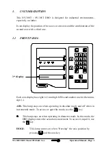
Page 8: ...1 1 FRONT PANEL 3rd display Each axis display has eight 14 1mm high LEDs and another one for the minus sign ABS This lamp stays on when operating in absolute mode and off when in incremental mode To...

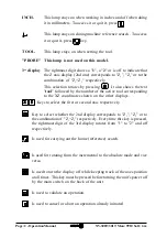
Page 9: ...owed by the number of the active tool corresponding to the XZ coordinates shown on the other displays Keys to select the first or second axis respectively Key to select whether the 2nd display corresp...

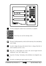
Page 10: ...is used for entering values and making a tool change Is used to change the sign of the entered value or change from fine to coarse resolution and vice versa This one is a dual purpose key and is also...

Page 11: ...this switch the DRO no longer reads axis position Therefore it is recommended to use the key at the front panel to turn the display off so the DRO continues keeping track of the axes position when the...

Page 12: ...ing the connectors mains feedback etc make sure that the unit is not under power It is NOT enough to turn the display off by using the key at the keyboard 1 3 GENERALCHARACTERISTICS Universal Power Su...

Page 13: ...nals NV 301T model Maximum frequency 250 KHz minimum separation between flanks 950nsec Phase shift 90 20 hysteresis 0 25 V Vmax 7V Maximum input current 3 mA High threshold logic state 1 2 4V VIH 5V L...

Page 14: ...r number if otherwise See the appendix at the end of this manual Turning the unit OFF If you press the DRO turns off the displays while maintaining the power supply to the feedback systems and goes on...

Page 15: ...hem With binary values The value of each digit toggles between 0 and 1 when pressing its corresponding key from to where corresponds to the rightmost digit and to the leftmost one Numeric values usual...

Page 16: ...Press the other axis key if it is an axis parameter to save the display value and go on to the editing it for the other axis selected To modify a parameter press ENTER to go on to the next one or 1 2...

Page 17: ...type Digit 8 Direction of the coded Io 0 Increasing 1 Decreasing 7 Pitch of the coded Io 0 20 mm 1 100mm 6 Type of linear scale s Io 0 Fix 1 Coded 5 Feedback resolution units 0 microns 1 inches 4 Not...

Page 18: ...olution as per the formula Encoder lines turn Leadscrew pitch mm turn Resolution mm pulse xF Where xF would be the multiplying factor to be applied PAR03 External multiplying factor for when using sem...

Page 19: ...and travel limit overrun alarms axis display blinking will be displayed if the corresponding bit of PAR08 1 The blinking axis error is cleared by returning the axis within its limits The speed alarm...

Page 20: ...the corresponding axis display starts blinking until it is moved back into the work zone This value will be in mm or inches depending on whether the INCH LED is off or on PAR13 To set the positive axi...

Page 21: ...onnectors one by one If the DRO comes on it indicates a fault in the feedback device If the fault persists get in touch with FagorAutomation s Customer Services Department about it Message Description...

Page 22: ...75 isotropic alcohol with a clean cloth DO NOT USE aggressive solvents benzol acetones etc which could damage the materials the equipment is made with Do not use high pressure compressed air to clean...

Page 23: ...FAGOR DRO NV 300T NV 301T OPERATION MANUAL Man 9910 Soft 2 xx...

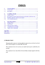
Page 24: ...in the installation manual supplied with this unit INDEX 1 Unit description 1 1 1 Front panel 1 1 2 Rear panel 4 2 Coordinate display 6 2 1 Display modes 6 2 2 Incremental absolute and with respect to...

Page 25: ...1 1 FRONT PANEL 3rd display Each axis display has eight 14 1mm high LEDs and another one for the minus sign ABS This lamp stays on when operating in absolute mode and off when in incremental mode To a...

Page 26: ...ed by the number of the active tool corresponding to the XZ coordinates shown on the other displays Keys to select the first or second axis respectively Key to select whether the 2nd display correspon...

Page 27: ...and is used for entering values and making a tool change Is used to change the sign of the entered value or change from fine to coarse resolution and vice versa This one is a dual purpose key and is a...

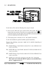
Page 28: ...power connector for AC and ground connection 3 M6 mm terminal for general machine ground connection Some of the following connectors might not be available depending on specific models X3 SUB D HD typ...

Page 29: ...Soft 2 xx WARNING Do not handle the connectors while the unit is under power Before handling the connectors mains feedback etc make sure that the unit is not under power It is NOT enough to turn the...

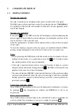
Page 30: ...rear panel on Notes Before powering the DRO down with the switch on the rear panel or discon necting it from mains it is a good idea to press the key in order to store the current position of the axes...

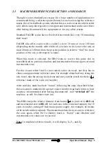
Page 31: ...e for the carriage Z1 and the other one for the compound Z2 When using two feedback devices the Z axis display may show the position of Z1 that of Z2 or the result from combining adding the positions...

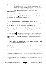
Page 32: ...he present position of the axis to part zero 0 is displayed In reference zero when led is on the distance from the present position of the axis to home Io chosen in the feedback system scale or encode...

Page 33: ...to reestablish all its previous absolute and incremental references part zero and incremental zero For this reason when fixed Io not coded scales are used one first has to choose an approximate refere...

Page 34: ...er PAR10 for this axis This value is factory set default 0 At the same time it recovers the relative distance from this home to the previously fixed part zero ABS and incremental When using semi absol...

Page 35: ...to the part zero point 0 in the figure although the DRO also shows them with respect to home Io After referencing the axes as was described in the previous section we can make this part in incrementa...

Page 36: ...ads 0 000 This last method turns out to be more practical as after selecting the destination coordinate one only has to remember to move the axis until the DRO reads zero Once this turning operation h...

Page 37: ...vious zero ABS and leds off to part zero ABS led on or with respect to home led on The next section describes how preset up to 10 tools 3 SPECIAL OPERATIONS 3 1 SCALING FACTOR With this DRO it is poss...

Page 38: ...at the known diameter Press and the TOOL led will come on to indicate that this mode has been selected The 3rd display will show the word tool followed by the number of the tool at the time Press the...

Page 39: ...t said point Press and the counting defreezes starting to count from the previously frozen value If in place of this 1 2 is pressed half of the value accummulated since the HOLD function was activated...

Page 40: ...nnectors one by one If the DRO comes on it indicates a fault in the feedback device If the fault persists get in touch with FagorAutomation s Customer Services Department about it Message Description...

Page 41: ...isotropic alcohol with a clean cloth DO NOT USE aggressive solvents benzol acetones etc which could damage the materials the equipment is made with Do not use high pressure compressed air to clean th...

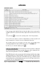
Page 42: ...or notice Message Description FAGOR dro Power outage or turned off by main switch after saving the data Error 02 Power outage or turned off by main switch without having saved the data The unit has be...

Reviews: