EN
62
4.2
Positioning and levelling
The place where the appliance is to be installed should be analysed prior to installation to check
that it is suitable.
The installation location must be able to withstand the weight of the machine.
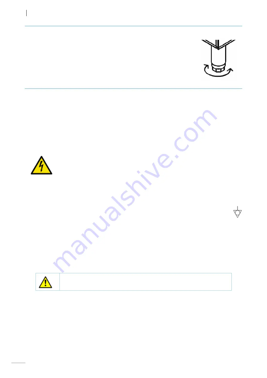
The height of the legs can be adjusted by turning them to ensure that the
appliance is correctly installed. It is essential that the machine is correctly levelled.
Electrical cables, water and drainage hoses must not be trapped or contain kinks.
4.3
Electrical connection
An
AUTHORISED TECHNICIAN
should always carry out the appliance’s electrical connection.
The legal standards in force regarding connection to the mains must be taken into account.
•
The specifications plate indicates the maximum power in kilowatts (kW) and amperes (A)
for the correct sizing of the installation components (line, power supply cable…). If the
configuration is changed, the values must be revised.
•
Check that the mains voltage corresponds to that indicated on the nameplate.
•
Flexible cable with oil-resistant coating, type H05RN-F or H07RN-F must be used.
•
The cross-section of the power cable must be suitable for the rated current of the machine.
•
It is obligatory to earth the appliance. Ensure that the earth connection operates correctly
and efficiently. The manufacturer will not be held liable for damage originated by failure to
observe this requirement.
•
Near the appliance and easily accessible to the user, between the power supply and the
appliance, a suitable omnipolar cut-off Circuit Breaker with a minimum contact separation of
3 mm (0,12 in) must be installed. This switch should be used to disconnect the appliance
during installation, repair, cleaning and maintenance work. It is recommended that it has
lockout-tagout capabilities. The manufacturer will not be held liable for damage originated
by failure to observe this requirement.
•
A suitable safety switch / Residual current device must be installed near the appliance
between the power supply and the appliance. The manufacturer will not be held liable for
damage originated by failure to observe this requirement.
•
The terminal marked with the symbol EQUIPOTENTIAL BONDING on the rear of
the machine must be used for the equipotential connection between different
appliances.
•
If any faults are observed during the installation, the supplier should be notified immediately.
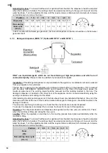
The voltage configuration of the machine is stipulated on the nameplate (FACTORY ELECTRICAL
CONNECTION
Fig. 6
). All the machines are equipped with a terminal box for configuring different voltage
and power/amperage options (230 V 1N~, 230 V 3~ or 400 V 3N~)
(Fig. 6).
To access the connection terminal, remove the front cover of the machine (
D, Fig. 1
). This allows the power
cable to be connected and the machine configuration to be changed if required
(Fig. 6)
.
If the configuration is modified, this should be indicated on the side of the nameplate using the labels
supplied.
The power cable must be secured using the packing glands (
C, Fig. 1
).
ONLY AUTHORISED AND QUALIFIED PERSONNEL may change the electrical
configuration. Users may not tamper with the machinery.
MOD “C”
has a menu which can be configured by the technical service to modify the
Alternate and
Simultaneous
heating values of the tank and boiler resistors so that they operate simultaneously or
alternately depending on the
CONNECTION Fig. 6. This value must be checked when the machine is
installed.
Chapter
4.7 ADJUSTING PARAMETERS (MOD “C”).
Summary of Contents for evoCONCEPT
Page 14: ...14 MOD A CO 142 MOD B COP 144 ...
Page 15: ...15 MOD C ...


