13
- A heating by-pass should be fitted to ensure that the above condition is satisfied. If thermostatic radiator
valves are to be installed, at least one radiator should be without a thermostatic valve (usually the bathroom
radiator).
- A sealed system must only be filled by a competent person using the approved method shown.
- The following paragraphs outline the specifications of the items fitted to the boiler.
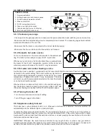
Expansion vessel.
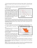
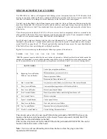
The following table gives the maximum system vol-
ume that the integral 7 l expansion vessel can sus-
tain under different temperature conditions. If the
system volume exceeds that shown, an additional
expansion vessel must be fitted and connected to
the heating system primary return pipe as close as
possible to the appliance. If an extra vessel is
required, ensure that the total capacity of both ves-
sels is adequate. If the pressure gauge indicates
2.65 bar or greater when the appliance is at maxi-
mum temperature with all radiators in circulation an
extra expansion vessel is required.
Pressure relief valve
A pressure relief valve set 3 bar (43.5psi) is fitted and a discharge pipe is routed to the outside of the appli-
ance. This discharge pipe should be extended to terminate safely away from the appliance to a point where
a discharge would not cause damage to persons or property but would be detected. The pipe should be able
to withstand boiling water, be a minimum of 15mm in diameter, and not include any upward pipe runs or hor-
izontal runs prone to freezing.
4.9 D.H.W. SYSTEMS
- Check that mains supply pressure is within the prescribed limits (refer to ‘technical data’ page 7) If neces-
sary, a pressure reducing valve should be fitted to the mains supply before D.H.W. inlet connection.
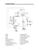
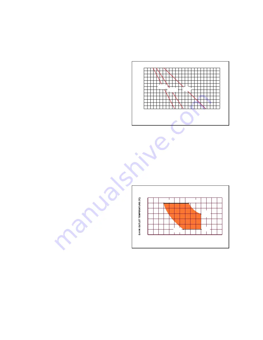
- The DHW performance is summarised in the
graph:
- The final 600 mm (24 in) of the mains supply pipe
to the boiler must be copper.
- If the appliance is installed in an area where the
temporary hardness of the water supply is high, say
over 150 ppm, the fitting of an in line scale inhibitor
may be an advantage.
- Devices capable of preventing the flow of expan-
sion water: e.g. non return valves and/or loose -
jumpered stop cocks should not be fitted unless sep-
arate arrangements are made for expansion water.
- If a non-return valve is fitted in the incoming water supply - e.g. in line with scale inhibitor then a D.H.W.
expansion vessel MUST be obtained and fitted.
- For specific information relating to fittings (eg. Shower, washing machines etc.) suitable for connection in the
D.H.W. circuit, consult the Local Water Undertaking, however the following information is given for guidance.
Domestic hot/cold water supply taps and mixing taps -
All equipment designed for use at mains water
pressure is suitable.
Showers -
Any mains pressure shower is suitable, but if the unit has a loose head which may become
immersed in bath water either an anti-syphonage device must be fitted, or the length of the flexible hose must
be reduced so that it cannot fall closer than 13 mm (1/2 in) to the top of the bat
50
100
150
200
250
1
1,2
1,4
1,6
1,8
2,0
2,2
P
C
85º C
75º C
60º C
P Cold pressure (bar)
C System capacity (litres)
4
35
30
2
1
3
60
55
40
50
45
35 °C
6.7 l/min
7
6
5
11
10
9
8
14
12 13
49 °C
10 l/min
60 °C
7.6 l/min
60 °C
3 l/min
35 °C
10 l/min
65
COLD WATER INLET TEMPERATURE =15ºC
FLOW D.H.W. (l/min)
D H W Performance graph


