AC Brushless Servo Drive System Manual Ver: 0002
ACa - 27 / 32
Preliminary
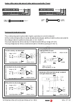
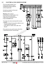
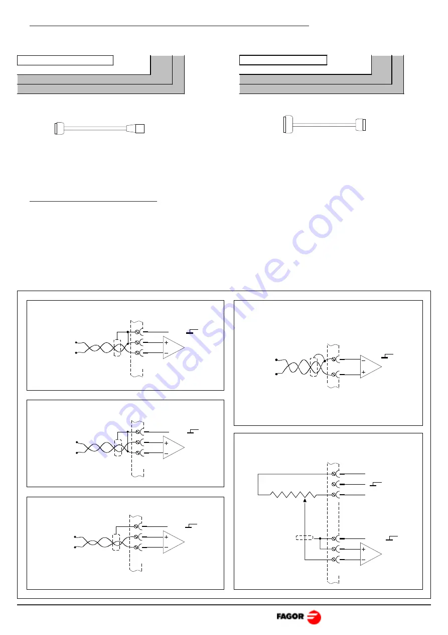
Command signal connection.
The command governing the motor may be a velocity or current command.
All the command signal lines must be shielded twisted pairs and the shield must be connected to
the voltage reference at the module (pins 2, 4 or 10 of X1).
The input impedance of the velocity command is 22 kOhms (a range of ±10 V).
The input impedance of the current command is 10 kOhms (a range of ±6.2 V).
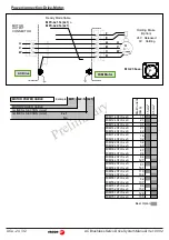
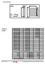
Codes of the sales references for the cables supplied by Fagor:
SUB-D
HD M15
IOC-17
SUB-D
M15
SUB-D
HD F15
5
4
6
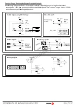
Differential velocity command input:
5
4
6
VEL+
VEL-
Inverted velocity command input:
Uref
0V
5
4
6
Uninverted velocity command input:
Uref
0V
4
7
CURR
C
u
rre
n
t co
m
m
a
n
d
Current command input:
Uref
0V
Generation of the inverted velocity command
and application to the drive:
5
4
6
Uref
2
1
3
-10 V
+10 V
10 k
Ω
range: ± 10V
range: ± 6.2 Vdc
Input impedance: 22 k
Ω
V
eloc
it
y
c
o
m
m
a
n
d
Input impedance: 10 k
Ω
Uref
0V
shortcircuit RAPT on the IM.
Jumper J4 (bc)
Jumper J4 (bc)
Jumper J4 (bc)
Jumper J4 (bc)
Jumper J4 (ab)
VEL+
VEL-
VEL+
VEL-
VEL+
VEL-
V
eloc
it
y
c
o
m
m
a
n
d
V
eloc
it
y
c
o
m
m
a
n
d
Input impedance: 22 k
Ω
Input impedance: 22 k
Ω
range: ± 10V
range: ± 10V
V
eloc
it
y
c
o
m
m
a
n
d
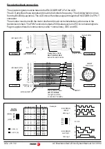
MOTOR ENCODER CABLE
Example: IEC - 20
INCREMENTAL ENCODER CABLE
LENGTH (m)
5, 10, 15, 20.
CNC ENCODER CABLE
Example: SEC - 20
SIMULATOR ENCODER CABLE
LENGTH (m)
1, 3, 5, 10, 15, 20.


