background image

AC Brushless Servo Drive System Manual  Ver: 0002

ACa - 7 / 32

Preliminary

Summary of Contents for FXM1 Series

Page 1: ...AC Brushless Servo Drive System Manual Ver 0002 ACa 1 32 Preliminary Fagor Automation S Coop Ver 0002 Brushless AC Servodrives analog ...

Page 2: ... CHARACTERISTICS 9 1 5 SALES REFERENCE 9 A C Servodrive 10 2 1 INTRODUCTION 10 2 2 GENERAL CHARACTERISTICS 11 2 3 CONNECTORS 11 2 4 STATUS DISPLAY 14 2 5 PLACA DE CARACTERÍSTICAS Y REFERENCIA COMERCIAL 15 2 6 INTERNAL OPERATION DIAGRAM 16 Identity Module IM 18 Installation 22 5 1 GENERAL CONSIDERATIONS 22 5 2 ELECTRICALCONNECTIONS 23 5 3 ELECTRICAL ENCLOSURE DIAGRAM 28 5 4 INITIALIZATIONANDSETUP 2...

Page 3: ...tocontactourtechniciansatany ofoursubsidiariesworldwide ThankyouforchoosingFagor Declaration of conformity Manufacturer Fagor Automation S Coop BarriodeSanAndréss n C P 20500 Mondragón Guipúzcoa SPAIN Weherebydeclare underourresponsibilitythattheproduct FagorACBrushlessServoDriveSystem consistingofthefollowingmodulesandmotors Servodrives ACSSeries ACMotors FXMSeries mentionedonthisdeclaration with...

Page 4: ...ake B5 V1 V3 Excitation Permanent rare earth magnets SmCo Temperature sensor Thermistor Shaft end Cylindrical with keyway Option with no keyway Mounting Face flange Mounting method B5 V1 V3 as recommended by IEC 34 3 72 Mechanical tolerances Normal class IEC 72 1971 Balancing Class N Class R optional DIN 45665 balanced with the whole key Roller bearings life 20 000 hours Noise DIN 45635 Vibration ...

Page 5: ...9 0 4 3 6 0 7 6 6 2 2 6 13 0 4000 4 2 21 0 1 1 0 6 19 3 4 9 1 1 6 0 7 6 6 2 2 0 10 0 2000 1 6 8 0 0 4 1 3 9 4 48 0 8 5 4 5 5 5 6 3 2 0 10 0 4000 3 2 16 0 0 8 0 6 18 8 13 0 2 4 4 5 5 5 3 1 6 3 3 9 19 5 2000 3 2 16 0 0 8 1 2 7 9 23 0 3 4 7 4 7 5 6 1 12 2 3 9 19 5 4000 6 3 31 5 1 6 0 6 15 9 5 8 0 8 7 4 7 5 6 2 12 4 5 8 29 0 2000 4 7 23 5 1 2 1 2 7 6 13 0 1 7 10 5 9 6 12 3 24 7 5 8 29 0 4000 9 4 47 0 ...

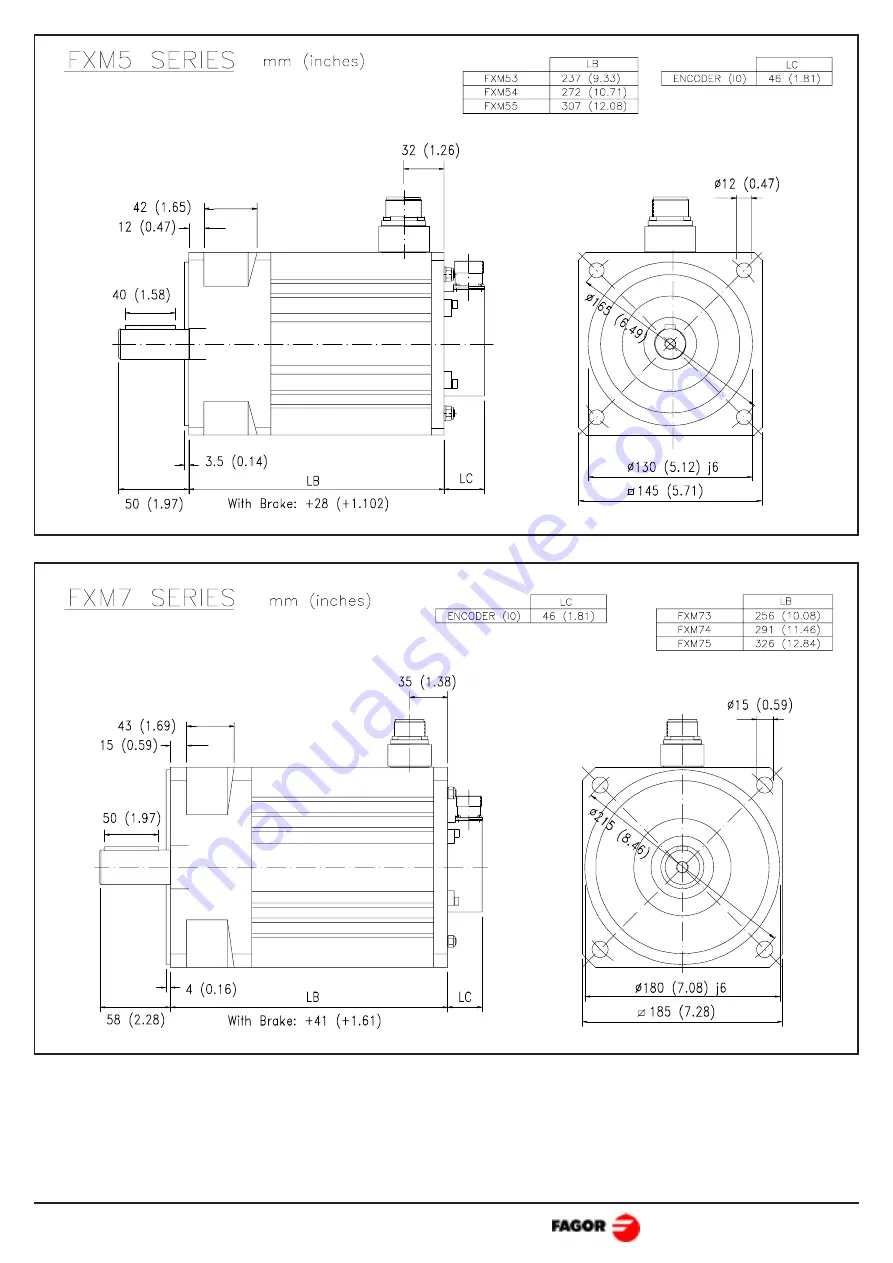
Page 6: ...AC Brushless Servo Drive System Manual Ver 0002 ACa 6 32 Preliminary 1 2 MECHANICAL DIMENSIONS ACMOTORS ...

Page 7: ...AC Brushless Servo Drive System Manual Ver 0002 ACa 7 32 Preliminary ...

Page 8: ...asetheshaft Wheninstallingthemotor verifythatthebrakereleasestheshaftcompletely before turning it for the first time Connecting the motor windings in the order indicated on the connector U V W the shaft will turnclockwise CWR Encoderconnector sterminals9and10correspondtothethermistor Itwatchesthemotor heating 1 3 POWER CONNECTORS AND ENCODER OUTPUT ...

Page 9: ...out Keyway BRAKE OPTION 0 Without brake 1 With standard brake 24 Vdc VENTILATION 0 Without Fan 1 5 SALESREFERENCE 1 4 BRAKE CHARACTERISTICS Motor Type Torque Maximum RPM Power On Off Delay Unlocking voltage margin Inertia Weight Nm in lb rpm W HP ms Vdc Kg cm2 lb in2 Kg lbf FXM 1 2 5 22 12 10000 12 0 016 7 5 22 26 0 38 0 13 0 3 0 66 FXM 3 5 44 25 8000 16 0 021 15 7 1 06 0 36 0 6 1 32 FXM 5 12 106 ...

Page 10: ...2500ppt Programmableencoderoutput2 n n from2to16 VelocityorTorquecommand Velocitycommandfilteredwithramps Logicinputstocontrolthemotor SpeedandDriveEnable Galvanicisolationbetweenpowerandcontrol Analogoutputstomonitorspeedandcurrent Controlagainstexcessiveacceleration deceleration 7 segmentdisplaytomonitorthestatusoftheservodrivesystem InternalfanactivationdependingontheDrive_Enablesignal Protecti...

Page 11: ... AuxiliarPowerSupplyterminals Themaximumcablesectionatthesepowerterminalsis 2 5mm2 Totalisolationbetweenpowerandcontrolcircuits Fagor A C S Drive ACS 05 ACS 10 ACS 20 ACS 30 Rated output current 2 5 Amp rms 5 Amp rms 10 Amp rms 15 Amp rms Peak output current 0 5 sec 5 Amp rms 10 Amp rms 20 Amp rms 30 Amp rms Power supply Three phasic mains 50 60 Hz from 220Vac 15 to 240Vac 10 Consumption Amp 2 5 A...

Page 12: ...mon Pin5ofX2 ReferencepointforthefollowingEnablesignals Drive Enable Pin 4 of X2 At 0Vdc disables current through the motor which loses its torque Speed Enable Pin 3 of X2 A 0Vdc forces a zero speed command Thesecontrolsignalsareactivatedat 24Vdc Drive OK Pines 6 7 of X2 Relay contact that closes when the internal status of the drive is OK Itmustbeincludedintheelectricalmaneuver Encoder Input Moto...

Page 13: ...lay Status and Alarm messages from the Status Display X1 Connector for the encoder input signals Connector for encoder signal output to CNC Auxiliar Power Supply input terminals Connectors and front panel CONTROL POWER INPUTS N L 9 8 10 VELOCITY CURRENT 7 6 DR OK 4 3 5 SPEED DRIVE COMMON 10 V 10 V 2 1 3 Vel Vel 5 4 6 7 CURRENT 10 V power Commands Monitoring Enables Drive OK COMMANDS CONTROL POWER ...

Page 14: ...tycycle Improveitscooling NoFeedback Solutions Checkthatthefeedbackcableandconnectorsareproperlyconnected Driveovertemperature Solutions Smooththedutycycle Improveitscooling Motoroverloadwarning fastblinking Themotori2tprotectionsisbeenexceeded Thiseventactivatesthedigitaloutput Warning output 1 and 2 pins of X2 60 seconds later the error will be activated Motoroverloaderror Afterthepreviouswarnin...

Page 15: ...t Internalcontrolerror ortheRITvalueiswrong Phase droped Any of the main phases has droped or a mains microcut has been longer than 100ms Note Allthealarmsarelatched theunit controlandpowersupply mustbepoweredoffand turnedbackonafter30seconds OrpushtheResetbutton 2 5 SPECIFICATIONS PLATE AND SALES REFERENCE Examplesofthe specsplatethatcomeswith eachFagorACSdrive Codes of the sales referenceofFagor...

Page 16: ...in 6 X2 Pin 7 X2 WARNING OUTPUT DRIVE SPEED Pin 3 X2 Offset RTV1 RIT RAPT J4 a b c A Pin 5 X2 Pin 4 X2 Control de PWM COMMON COMMON RAD1 CAD1 RAP1 CAI1 RAJFV VEL VELOCITY Pin 8 X1 Pin 5 X2 B3 B0 RTV1 Protections Feedback Error Drive Overtemperature Motor Overload Drive Overcurrent Drive Overvoltage Undervoltage Balast overload Internal Fault Power Supply Fault X1 W U V L Ri Re Pin 10 X1 Rectifer P...

Page 17: ...AC Brushless Servo Drive System Manual Ver 0002 ACa 17 32 Preliminary User notes ...

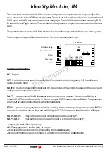
Page 18: ...esoftheencoderpulsesandtheequivalent voltageintheinternaldrivecircuits RAPT ItdeterminesiftheBallastisaninternalorexternalresistor IfanexternalBallastis installedRAPTshouldbeequalto 10 Ohms AnopenRAPTmeansinternalBallast Theprotection againsti2texceedingdoesn tworkwithexternalBallast RTV1 notavailableyet Itsetsthedriveacordingtotheencoderpulsesperturnused IfRTV1 is short circuited the drive will b...

Page 19: ...xx0 IM 3140F 05 IM 3140F 10 220K 6 2K FXM32 20F I0 xx0 IM 3220F 05 IM 3220F 10 220K 12K FXM32 40F I0 xx0 IM 3240F 10 IM 3240F 20 68K 6 2K FXM33 20F I0 xx0 IM 3320F 10 IM 3320F 20 100K 12K FXM33 40F I0 xx0 IM 3340F 20 39K 6 2K FXM34 20F I0 xx0 IM 3420F 10 IM 3420F 20 68K 12K FXM34 40F I0 xx0 IM 3440F 20 18K 6 2K FXM53 20F I0 xx0 IM 5320F 20 IM 5320F 30 47K 12K FXM53 40F I0 xx0 IM 5340F 30 12K 6 2K ...

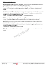
Page 20: ...ch correspondstothemaximumvalueofthecurrentcommand Thisadjustmentmaybeusedto decrease 100 thevalueofthatcurrentlimit Turningthispotclockwiseallowsmorecurrenttoflowthroughthemotor PIGain ForadjustingtheoverallgainofthevelocityPI Turningthispotclockwiseincreasesthegainand therefore makesthesystemperkier Max Speed Everydriveisfactorysetsothemotorturnsatitsmaximumspeedwhenapplied maximumvelocitycomman...

Page 21: ...AC Brushless Servo Drive System Manual Ver 0002 ACa 21 32 Preliminary User notes ...

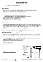
Page 22: ... pollutants rememberthatitsdegreeofprotectionisIP20 Neverinstallitexposingittoflammable gases Avoidexcessiveheatandhumidity Theambienttemperaturemustneverexceed45 C 113 F Mountthemodulesvertically asshownonthephotos Avoidvibrations Leaveatleast30cmofclearanceaboveandbelow themoduleforbetterairflow Abouttheconnections All the cables must be shielded to reduce the interference on the control of the ...

Page 23: ...lledontheMains inputlines theirmaximumcurrentswilldependonthevalueoftheMainsvoltage Athermalswitchmayoptionallyreplacethefuses Important Thesecondarywindingsmusthaveastarconnectionwithitsmiddlepointconnected toground POWER INPUT L3 L1 L2 Autotransformer ACS Drive Mains 3 x 2 5 mm2 Fuses Secondary 3x220 Vac From to kw ACS 05 ACS 10 4 Amp Transformer Fuses 3 x 2 5 mm2 Fuses Secondary 3x220 Vac From ...

Page 24: ... 40F I0 xx0 3 1 FXM14 20F I0 xx0 2 1 FXM14 40F I0 xx0 4 2 FXM31 20F I0 xx0 1 6 FXM31 40F I0 xx0 3 2 FXM32 20F I0 xx0 3 2 FXM32 40F I0 xx0 6 3 FXM33 20F I0 xx0 4 7 FXM33 40F I0 xx0 9 4 FXM34 20F I0 xx0 6 4 FXM34 40F I0 xx0 12 7 FXM53 20F I0 xx0 8 1 FXM53 40F I0 xx0 16 1 FXM54 20F I0 xx0 11 0 FXM54 30F I0 xx0 16 4 FXM55 12F I0 xx0 8 2 FXM55 20F I0 xx0 13 7 FXM73 12F I0 xx0 9 4 FXM73 20F I0 xx0 15 7 ...

Page 25: ...A 125Vac 0 6A 110Vdc 2A 30Vdc Enable signals using 10V voltage X1 SPEED DRIVE COMMON 2 1 3 10 V 10 V X2 X2 4 5 X2 X1 3 Connectionofthemonitoringandcontrolsignals Monitoring Thedriveoffers 10Vdcatits velocity outputwhen receivingthemaximum commandof 10V themotorturnsatthecalculatedspeed The current outputoffers 10Vdc whenthedriveprovidesitspeakcurrent Warning Output 2 1 X2 C E 24 Vdc 2 1 X2 C E 24 ...

Page 26: ...C 1 3 5 10 15 20 1 2 3 4 5 6 7 8 11 Sub D M15 8 1 15 9 Sub D M15 4x2x0 14 2x0 5 Cable A A B B Z Z 5 Vdc W Tp V 1 2 3 4 5 6 7 8 11 10 15 12 13 14 9 GND Tp U U V W 14 15 16 9 4 3 11 10 9 8 6 12 13 14 15 16 17 10 HD Sub D M15 IOC 17 IOC 17 To Drive To Drive To Motor To Control Front view Green Yellow Blue Purple Grey Pink Brown White Black Length in meters connectors included Green Yellow Blue Black ...

Page 27: ...input 5 4 6 VEL VEL Inverted velocity command input Uref 0V 5 4 6 Uninverted velocity command input Uref 0V 4 7 CURR Current command Current command input Uref 0V Generation of the inverted velocity command and application to the drive 5 4 6 Uref 2 1 3 10 V 10 V 10 kΩ range 10V range 6 2 Vdc Input impedance 22 kΩ Velocity command Input impedance 10 kΩ Uref 0V shortcircuit RAPT on the IM Jumper J4 ...

Page 28: ...es a simple circuit to power the brake of the FXM Warning When using an autotransformer thesecondarymust haveastarconnectionwithits middlepointconnectedtoground FusesareMANDATORY ThedelaywhendisconnectingtheD3contacts servesfor the Drive_Enable tostayactivewhilethemotor isbrakingatmaximumtorque for the brake to hold the motor after it has stopped Ifthesystemmovesaverticalaxis itshouldbe compensate...

Page 29: ...ntiometertoadjustthemaximumpeakcurrent maximummotor torque To monitor the peak current the motor may be turned back and forth at full torque and withoutgeneratingramps AdjustthegainofthevelocityPIwiththe PI Gainpotentiometeruntilthedesiredbehavioris obtained Adjustthevelocityoffset Send to the drive an analog voltage of 0 Volts by jumpering pins 4 5 and 6 of X1 connector Measurethemotorspeedandtur...

Page 30: ...F 10 IM 7512F 30 FXM33 40F I0 xx0 IM 3220F 10 FXM34 20F I0 xx0 IM 3240F 10 FXM34 40F I0 xx0 IM 3320F 10 FXM53 20F I0 xx0 IM 3420F 10 FXM53 40F I0 xx0 IM 3240F 20 FXM54 20F I0 xx0 IM 3320F 20 FXM54 30F I0 xx0 IM 3340F 20 FXM55 12F I0 xx0 IM 3420F 20 FXM55 20F I0 xx0 IM 3440F 20 FXM73 12F I0 xx0 IM 5320F 20 FXM73 20F I0 xx0 IM 5420F 20 FXM74 12F I0 xx0 IM 5512F 20 FXM75 12F I0 xx0 IM 7312F 20 IM 741...

Page 31: ...is sheet has not been sent to us the warranty period ends 15 months from when the product left our warehouse FAGOR is committed to repairing or replacing its products from the time when the first such product was launched up to 8 years after such product has disappeared from the product catalog It is entirely up to FAGOR to determine whether a repair is to be considered under warranty EXCLUDING CL...

Page 32: ...x 285273 California FAGOR AUTOMATION West Coast 3176 Pullman Suite 110 Costa Mesa CA 92626 Tel 1 714 9579885 9892 Fax 1 714 9579891 caservice fagor automation com New Jersey FAGOR AUTOMATION East Coast Tel 1 973 7733525 Fax 1 973 7733526 wnelson fagor automation com CANADA Ontario FAGOR AUTOMATION ONTARIO Unit 3 6380 Tomken Road MISSISSAUGA L5T 1Y4 Tel 1 905 6707448 Fax 1 905 6707449 sales fagorau...

Reviews: