3-phase servomotors. FKM
3-
PHASE SERVOM
O
TORS. FKM
Co
nne
ctio
ns
3.
Ref.2105
· 117 ·
FXM|FKM
SERVOMOTOR
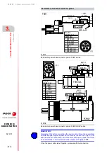
Servomotor power connection
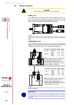
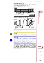
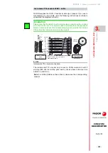
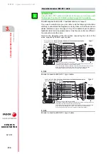
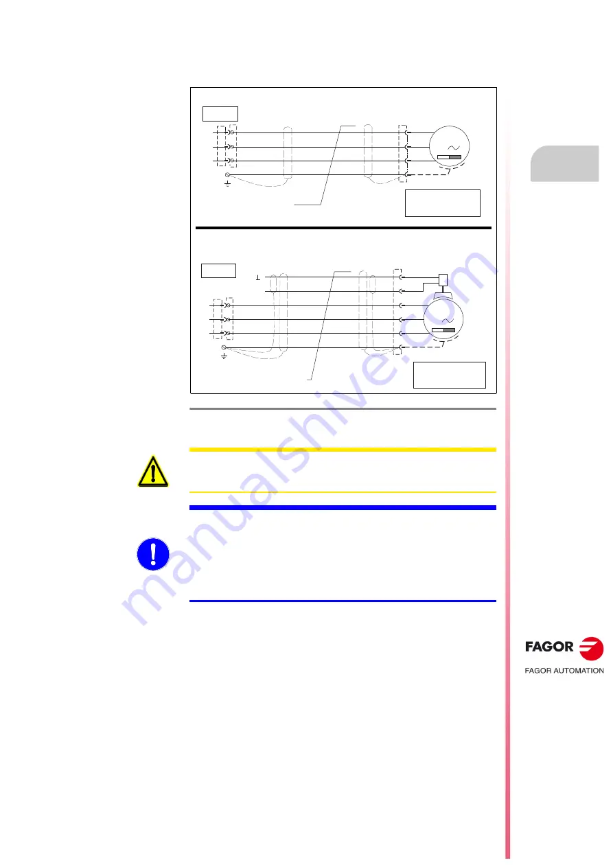
The power connection between the servomotor and the drive will be made
using the MPC power cable as shown in the diagram:
In order for the system to comply with the European Directive 2014/30/EU
on Electromagnetic Compatibility, the cable grouping the wires that make
up the power cable must be shielded.
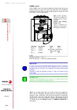
The shield must be connected to
ground at the drive end and at the servomotor end
as shown in figure
. This condition is a must.
F- 3/19
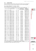
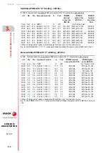
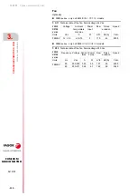
Power connection diagram between an FKM1/2/4/6/6V servomotor and a
drive.
0&
8
9
:
8
9
:
0
8
9
:
8
9
:
0
3(
3(
8
9
:
8
9
:
0
8
9
:
8
9
:
0
3(
3(
8
9
:
8
9
:
0
8
9
:
8
9
:
0
3(
3(
+ROGLQJ
EUDNH
2SWLRQ
:LWKEUDNH03&[PPð[
&DEOHZLWKRXWFRQQHFWRUV
8
9
:
'5,9(
9'&
8
9
:
0
&KDVVLV
6KLHOG
8
9
:
8
9
:
0
3(
).09
027256
3(
8
9
:
8
9
:
0
3(
8
9
:
8
9
:
0
3(
0&
8
9
:
8
9
:
0
8
9
:
8
9
:
0
3(
3(
8
9
:
8
9
:
0
8
9
:
8
9
:
0
3(
3(
%UDNHOHVV03&[PPð
&DEOHZLWKRXWFRQQHFWRUV
8
9
:
'5,9(
8
9
:
0
&KDVVLV
6KLHOG
8
9
:
8
9
:
0
3(
3(
8
9
:
8
9
:
0
8
9
:
8
9
:
0
3(
3(
).09
027256
8
9
:
8
9
:
0
3(
8
9
:
8
9
:
0
3(
FKM1/2/4/6/6V servomotors, with holding brake
Brakeless FKM1/2/4/6/6V servomotors
| MC-30/6
| MC-30/6
WARNING.
Never connect the servomotor directly to three-phase mains. A direct
connection will destroy it.
MANDATORY.
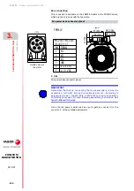
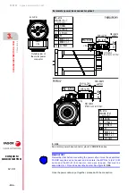
When connecting the drive module and the corresponding FKM
servomotor, connect the U terminal of the power connector to the terminal
corresponding to the U phase (pin 1) of the servomotor. Do the same for
terminals V-V (pin 2), W-W (pin 6) and PE-PE (pin 3).
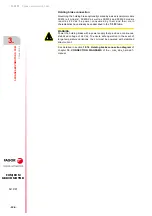
If the servomotor has a holding brake, connect pin 4 to a 24 Vdc supply
and pin 5 to a 0 Vdc supply from an outside stabilized power supply.


