background image

QCIG-10/16

Q

uer

C

us SERCOS-II Drive System. 

I

nstallation

 G

uide. Ref.1801/B

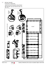
7.2

Mechanical installation

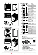
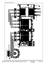
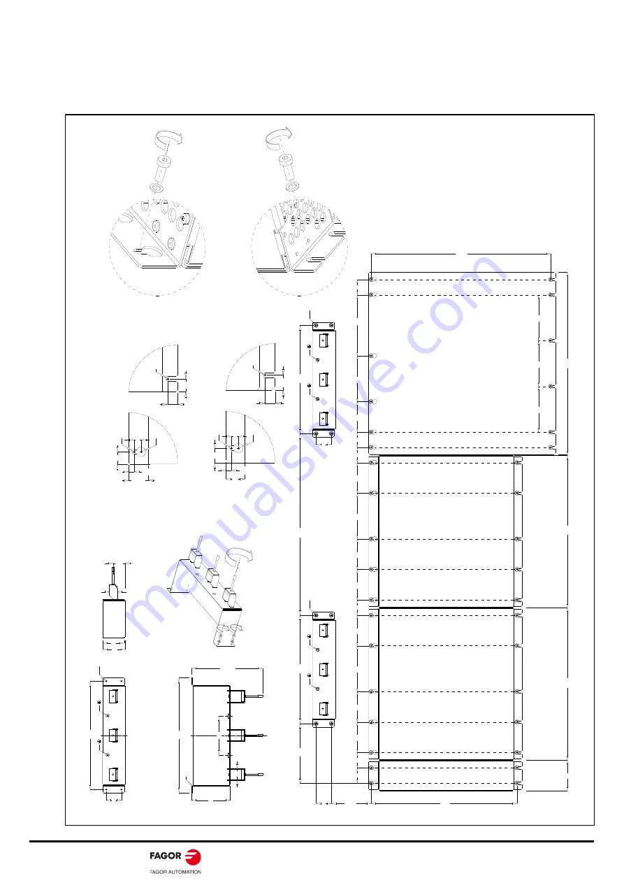
Preparing the mounting fixtures

Use the holes and slots prepared for the purpose of
fastening the equipment. Vibrations should be avoided.
Where necessary, use shock-absorbing lanyards. See
figure below.

373

39

39

78

78

117

78

78

78

78

117

39

77

38

9

389

46

7

39

39

39

156

117

78

QC-APSS-15

QC-DR-275-SS2

QC-RPS-160-SN0

LIM 160

39

277

M6

R2.75

M6

39

277

M6

R2.75

M6

152


>

1

00

46

4

39

277

99

55

R2.75

58

294

thickness 1.

50

M6

M6

max.182

100

20

28

31.5

117

117

117

459.5

R3

12.4

R3

24

7.1

R6

9

19

19

LIM 160

R3

12.4

R3

25.5

7.1

R6

9

19

19

QC-APSS-15 / QC-DR-275-SS2 / QC-RPS-160-SN0

1 N·m max.

3 N·

m

M5

RECOMMENDED 

WASHER  DIN 125, M5

M5

3 N·m

RECOMMENDED 

WASHER  DIN 125, M5

3 N·m

M5

Summary of Contents for QC-PDS SERCOS-II

Page 1: ...FAGOR AUTOMATION Ref 1801 B QC PDS Installation guide Original instructions FAGOR AUTOMATION DRAFT SERCOS II...

Page 2: ...damage caused by the influence of other nearby equipment EC Declaration of Conformity and Warranty Terms The warranty terms may be requested from your Fagor Automation representative or through the us...

Page 3: ...rning may mean not complying with some safety regulation INFORMATION symbol Notes warnings advises and recommendations Ground protection symbol It indicates that that point must be under voltage i INF...

Page 4: ...tion E21D Direct feedback connection A17 connection terminals of the DC BUS under the lid A18 24 V DC electric power supply input U V W E21D E21 X6 X5 X12 do NOT install X34 do NOT install X13 X1 Vers...

Page 5: ...following radio interference categories EN 61800 3 category C3 4 Dimensions 4 1 Auxiliary power supply QC APSS 15 4 2 Spindle drive QC DR 275 SS2 Connector Function A59 Fan power supply and disconnec...

Page 6: ...data A18 A20 A59 X12 X13 X33 X34 X35 X60 LIM 160 X60 QC RPS Tightening torque min max 0 5 0 6 N m Section 1 mm Screwdriver flat head 0 6x3 5 mm Length to strip 8 mm Tightening torque min max 0 5 0 6 N...

Page 7: ...st reference Storage Ambient temperature Acc to IEC 60721 3 1 IEC 61800 2 1K4 25 C to 60 C Transport Damp heat test steady state Acc to IEC 60068 2 78 IEC 61800 5 1 P supply disconnected 40 C 2 C and...

Page 8: ...ross section of the conductor wires connected to the power supply terminals Comply with local regulations on grounding WARNING The system must always be installed before applying voltage according to...

Page 9: ...order to reduce radiated emissions Use simple shielding for the motor encoder cable The system complies with current regulations regarding immunity with simple shield MANDATORY Installations of large...

Page 10: ...See figure below 373 39 39 78 78 117 78 78 78 78 117 39 77 389 389 467 39 39 39 156 117 78 QC APSS 15 QC DR 275 SS2 QC RPS 160 SN0 LIM 160 39 277 M6 R2 75 M6 39 277 M6 R2 75 M6 152 1 00 464 39 277 99...

Page 11: ...ssories are designed for the purpose of making DC power bus connections between the QC DR 275 SS2 and QC RPS 160 SN0 equipment and tighten the DIN 6923 M10 nuts See figures 1B 2B 1B 2B 24 N m 24 N m 2...

Page 12: ...DC currents This requires the use of a differential breaker Electrical connections Single pole power cables The range of single pole shielded MPC 1xS power cables supplied on request by FAGOR to make...

Page 13: ...minal box and to the grounding plate in the electrical cabinet L1 L2 L3 PE S 2 MPC 1xS MPC 1xS FM9 SPINDLE MOTOR QC APSS 15 QC DR 275 SS2 QC RPS 160 SN0 LIM 160 It is not necessary to remove the lid f...

Page 14: ...m m 2 Sy stem co nnect ion d iagram I n t e r n a l B u s W i r e R i b b o n C a b l e P O W E R D C B U S w i t h Q C R P S 1 6 0 S N 0 I N O U T X 1 X 1 R S 2 3 2 S e r i a l l i n e i n t e r f a...

Page 15: ...D S1 MECHANICAL MAIN SWITCH KM1 GND Q1 DIFFERENTIAL BREAKER EARLY OPEN CONTACT KA3 2 KA3 1 24VDC AT X35 3 RPS ENABLE 24VDC OFF DELAY TIMER KA3 OFF DELAY CONTACT OFF DELAY CONTACT 3x 400 480 VAC FUSES...

Page 16: ...ation Guide Ref 1801 B Code 14460253 Fagor Automation S Coop B San Andr s 19 Apdo 144 E 20500 Arrasate Mondrag n Spain Tel 34 943 719 200 34 943 039 800 Fax 34 943 791 712 E mail info fagorautomation...

Reviews: