Q
uer
C
us SERCOS-II Drive System.
I
nstallation
G
uide. Ref.1801/B
QCIG-3/16
1
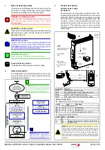
Notes of operating safety
Carefully read the following instructions before using the
servomotor. In these instructions, the operating safety
conditions are identified by the following labels.
2
System description
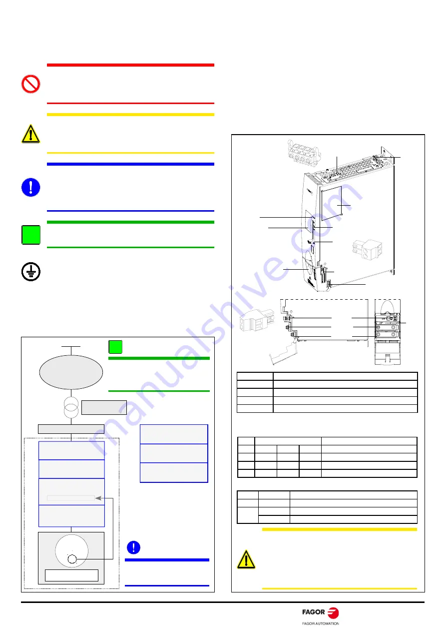
The configuration of the QC-PDS system for the control
of an asynchronous motor of the spindle follows the
following general diagram:
3
Product description
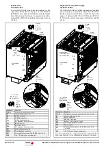
Auxiliary power supply.
QC-APSS-15
Its main function is to generate a voltage of +24 V DC,
required to feed the QC-DR-275-SS2 drive control circuits
and the QC-RPS-160-SN0 main power supply, connected
to the DC BUS. This voltage is supplied via the A18
connector, which is only accessible under the cover
located at the bottom of the module on the front of the
equipment. This auxiliary power supply includes
protection against output over-current, over-voltage and
short-circuits.
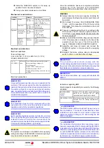
DANGER or prohibition symbol.
It warns about an immediate dangerous situation. Ignoring
t h i s w a r n i n g m a y c a u s e s e r i o u s , e v e n f a ta l ,
consequences.
WARNING or caution symbol.
It warns about a potentially dangerous situation. Ignoring
this warning may cause serious injuries (even fatal) or
damages to the unit.
MANDATORY symbol.
It warns about actions and operations that MUST BE
carried out. In other words, THEY ARE NOT PLAIN
RECOMMENDATIONS. Ignoring this warning may mean
not complying with some safety regulation.
INFORMATION symbol.
Notes, warnings, advises and recommendations.
Ground protection symbol.
It indicates that that point must be under voltage.
i
!
"
#
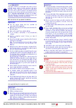
INFORMATION.
An additional mains filter may
also be installed (if required) for installations
that include a line interface module- Do so
always according to the indicated position.
MANDATORY.
Do not install additional
mains CHOKES for installations that
include a
L
ine
I
nterface
M
odule ·LIM·.
i
Status indicator LED’s
Associated with the +24 V DC voltage
Associated with the DC BUS
Connector
Function
X33
Activating the system soft-start
A17
+/-
connection pins of the DC BUS under the lid
A18
+24 V DC electric power supply output
A20
3-ph. power input to the auxiliary power supply
Leds
Color
Function
red
amber green
D1
ON
x
x
Overvoltage
D2
ON
x
x
Overcurrent
D3
x
x
ON
In the presence of +24 V DC
Leds
Color
Function
red
D7
ON
Signals the presence of voltage in the DC BUS
OFF
Read warning
WARNING.
The DC bus discharge period may extend for up to 10
minutes after the equipment has been disconnected from the
electrical mains. There is no assurance that there is no voltage in
the DC bus when the D7 led is turned off. Accordingly, never
handle the DC bus even when the D7 led is turned off. Always
ensure that there is no voltage in the DC bus before handling the
equipment.
X33
Name
plate
A20
Version/Model
label
D1,
D2, D3
RESET.
Auxiliary power supply
initialization button
Opening and
closing click cover
with bottom pivot
hinge
A18
A17
D7
A17
A18
+
-
A18
3 N·m
Ground
screw, M5

