Q
uer
C
us SERCOS-II Drive System.
I
nstallation
G
uide. Ref.1801/B
QCIG-9/16
EMC instructions for equipment installation
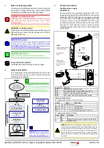
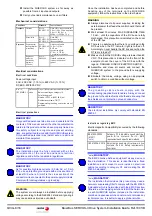
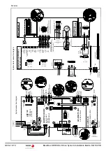
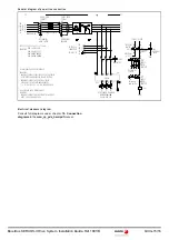
Use equipotential wires in systems with:
Repair
* note)
MANDATORY.
This type of PDS is not intended to be used on a low-
voltage public network which supplies domestic
premises. Radio frequency interference is expected if
used on such a network. However, equipment whose
compliance with the essential requirements set out in
item
1. General requirements
of annex I of the EMC
Directive that are not ensured in residential areas will
include an indication with this use restriction.
MANDATORY.
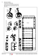
Use the copper plates that are provided as
accessories in the assembly.
Make the connections with wide contact surfaces for
the metal parts.
Remove the paint from contact surfaces.
Try to increase conductivity on two-dimensional
contacts.
Install a protection circuit if there is a risk of
overvoltage.
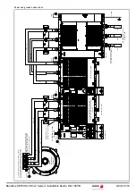
Route the electrical energy supply lines from the lines
carrying the information.
Note. The electrical field which could induce voltage
spikes on the information lines decreases with
distance.
Route the motor cable at a distance of at least 20 cm
from the signal cable or use shielding plates between
the motor cable and signal cable.
Do not run field bus cables and signal through a single
conduit with DC and AC lines with voltages over 60 V.
The field bus cables, signal lines and analog lines can
be installed in a same conduit.
Recommendation. Separate the conduits where the
cables are running at least 20 cm and make them as
short as possible. Do not install unnecessary cable
loops and use short cables from the central ground
point for connecting to a ground point outside the
electrical cabinet.
Avoid induction loops by choosing common routes for
power, signal and data circuit cables.
Use shielded cables for power supply and motor.
On shielded cables, the unshielded portion of the
cable used to connect them to the connectors must be
as short as possible in order to reduce radiated
emissions.
Use simple shielding for the motor encoder cable. The
system complies with current regulations regarding
immunity with simple shield.
MANDATORY.
Installations of large areas.
Different voltage sources.
Mains through several buildings reducing the current
in the cable shield and the emissions. Connect to
ground the electrical cabinet, the door, the mounting
plate, with ground straps or cables with a cross section
larger than 10 mm² (AWG 6).
MANDATORY.
The ground shields of the digital signal wires must be
connected at both ends to a large surface or through
a conductive housing of the connector. This reduces
disturbances that affect the signal cables and also the
emissions.
The ground shields of the analog signal wires must be
connected directly to the device (signal input),
reducing the ground loops due to low frequency
disturbances.
When a unit does not have a ground connection, the
shield must be connected on the side of the unit
connected to ground.
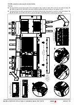
To connect large cable shield surfaces, use cable and
ground clamps.
Run a single shielded cable, in one piece, without
joints. If a cable must necessary be cut for the
installation, connect it with the shield connections and
through a metal cover at the cut (joint) point. In the
worst case, if it is not possible to use shielded
connectors, keep a minimum length of cable exposed
to disturbances guaranteeing a good connection
between the shields.
Mount switching devices such as contactors, relays
or electro-valves with interference suppression
elements or arc suppressors (e.g. diodes, varistors,
RC circuits).
Install power and control components separately.
Use equipotential cables when having long lines to
reduce the current through the cable shield.
When connecting power cables, the shield of this
cable should be connected to a ground bar.
DANGER.
Neither the user nor the machine manufacturer is
authorized to modificate or repair the drive, not even
to replace boards.
In the event that any safety function suffers a failure,
replace the drive with the same model of the same
version or later and set identical parameters on the
replacement model.
Conduct the partial acceptance test.

