Auxiliary modules
4.
AUXILIARY MODULES
Externa
l Au
xilia
ry Pow
er Su
ppli
es
174
Ref.2003
· 152 ·
QC-PDS
HARDWARE
4.6
External Auxiliary Power Supplies
Available models:
QC-APS-15
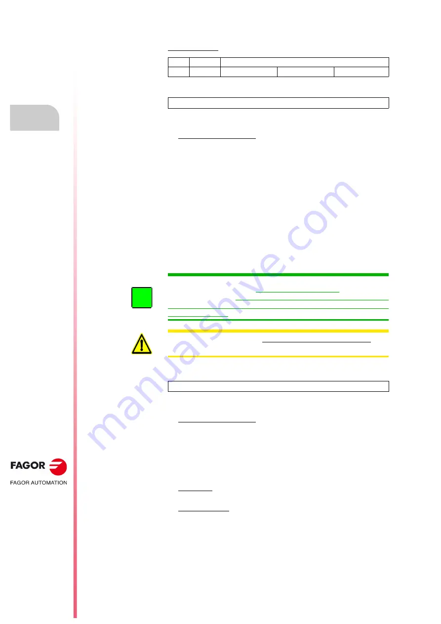
The QC-APS-15 commercial module is an external auxiliary power supply
whose main function is:
To supply the +24 V DC required to feed the control circuits of the
QC-PS-45 main power supply, as well as those of the QC-DR modular
drives connected to the DC BUS. This voltage is supplied via the A18
connector, which is only accessible under the cover located at the
bottom of the module on the front of the equipment. This auxiliary
power supply includes protection against output over-current, over-
voltage and short-circuits.
As a general rule, a QC-APS-15 power supply is not required when
installing a QC-PS-025 non-regenerative main power supply. An auxiliary
power supply is already integrated with this features. When the required
consumption of the entire system exceeds that being supplied by the
integrated auxiliary power supply, then one must be installed. Hence, for
example, when there are too many axes connected to the DC BUS, there
will be too many control circuits, fans etc. to supply power to. Therefore,
install a QC-APS-15 auxiliary power supply to provide all of the required
consumption.
QC-APS3-15
The QC-APS3-15 commercial module is an external auxiliary power
supply whose main function is:
To supply the +24 V DC required to feed the control circuits of the
QC-RPS-
-
regenerative main power supplies, as well as those of
the QC-DR modular drives and the QC-BPM-100 bus protection
module (if applicable) connected to the DC BUS. This voltage is
supplied via the A18 connector, which is only accessible under the
cover located at the bottom of the module on the front of the
equipment. This auxiliary power supply includes protection against
output over-current, over-voltage and short-circuits.
Gently start the QC-RPS-
-F
regenerative main power supplies using
the soft-start circuit.
Protect the motor against voltage peaks using the integrated
·
snubber
·
circuit.
A second QC-APS-15 power supply may also be installed next to it when
the required consumption of the entire system exceeds being supplied by
the QC-APS3-15 auxiliary power supply. Therefore, for example, when
there are too many axes connected to the DC BUS, there will be too
many control circuits, fans, etc. to supply power to. Therefore, install a
QC-APS-15 auxiliary power supply in parallel to provide all of the required
consumption.
size
width
references
0
39 mm
QC-APS-15
QC-APS3-15
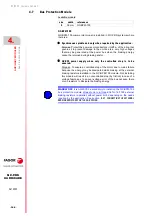
NOTE.
ALWAYS install whenever there is a QC-PS-045 power supply.
INFORMATION.
All of the installed QC-APS-15 auxiliary power supplies
can be connected in parallel on the same DC power bus using the under
cover (A17 terminals). The auxiliary power supply must only be connected
to the DC BUS when dynamic motor braking is required in the event of a
mains power outage.
WARNING.
NEVER connect the 24 V DC under cover outputs (A18
connector) between installed QC-APS-15 auxiliary power supplies.
i
NOTE.
ALWAYS install whenever there is a QC-RPS-
-
power supply.
Summary of Contents for QC-PDS
Page 1: ...DRIVE QC PDS Hardware manual Ref 2003...
Page 6: ...6 I 6 Ref 2003 6 QC PDS HARDWARE This page intentionally left blank...
Page 16: ...16 Ref 2003 16 Previous I QC PDS HARDWARE This page intentionally left blank...
Page 18: ...18 Ref 2003 18 Previous II QC PDS HARDWARE This page intentionally left blank...
Page 80: ...2 POWER SUPPLIES Power supplies 80 Ref 2003 QC PDS HARDWARE...
Page 138: ...3 DRIVES Drives 138 Ref 2003 QC PDS HARDWARE...
Page 174: ...4 AUXILIARY MODULES Auxiliary modules Ref 2003 174 QC PDS HARDWARE...
Page 302: ...8 INSTALLATION Installation Ref 2003 302 QC PDS HARDWARE...
Page 366: ...12 COMMERCIAL MODELS Commercial models Ref 2003 QC PDS HARDWARE 366...
Page 367: ...ANNEXES...
Page 368: ...ANNEX A1...
Page 383: ...ANNEX A2...
Page 398: ...ANNEX A3...
Page 418: ......
Page 419: ......


