Cables
7.
CABLES
Powe
r cab
les. D
R
IVE|MOTOR co
nnectio
n
· 220 ·
230
Ref.2003
QC-PDS
HARDWARE
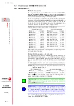
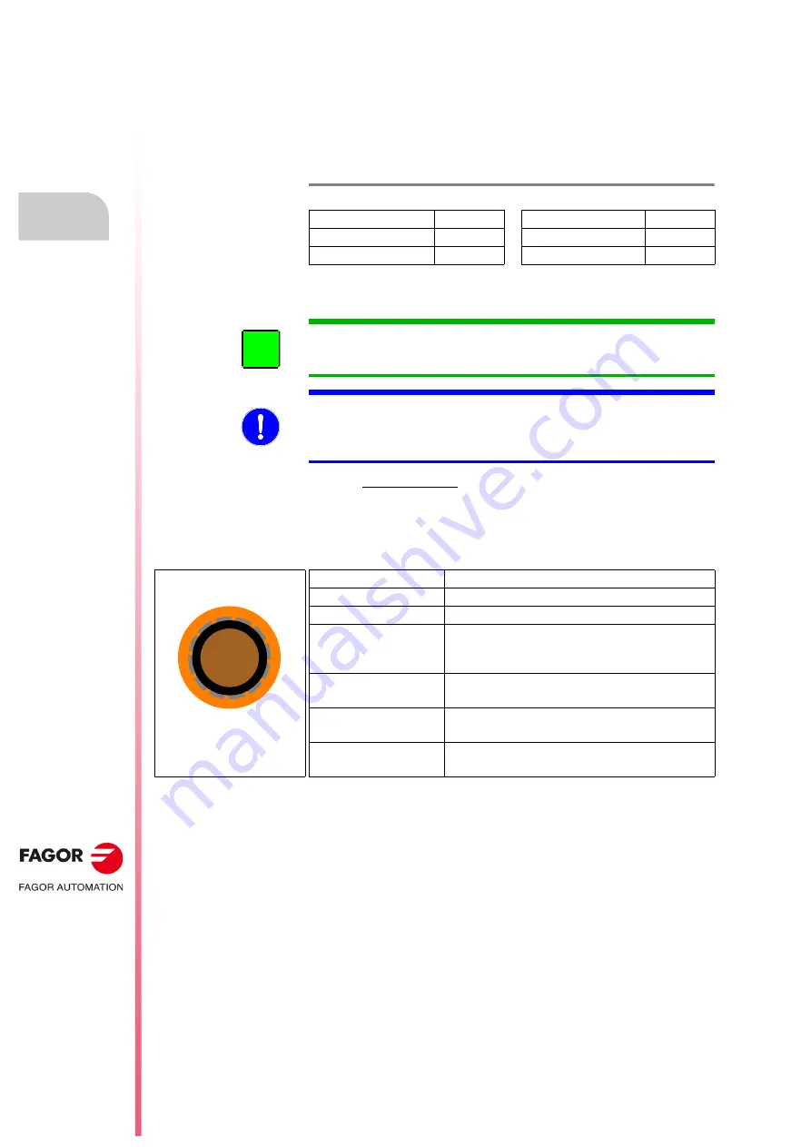
7.2.2 Single-pole cables
The range of MPC-1xS-
M single-pole power cables supplied by FAGOR
to establish the connection between the motor and the drive is shown in
the table
These are supplied without any pins. The number of cable meters is
available on request. Available lengths: 5, 10, 15, 20, 25, 30, 35, 40, 45 and
50 meters for 95, 120 y 150 mm² sections.
Supplied without terminals on the end and only upon request Therefore,
before making the connection, the corresponding terminals must be mount-
ed on the cable ends.
Characteristics
Selection
The required cable used to make the power connection between the drive
and the corresponding motor is shown in the motor-drive matching tables
in chapter
of this manual.
Installation
See section,
T. H7/6
Range of single-pole power cables. Outside diameter.
Reference
e approx.
Reference
e approx.
MPC-1x
95
-
M
22.0 mm
MPC-1x
150
-
M
25.8 mm
MPC-1x
120
-
M
23.6 mm
MPC-1x
S
, S: cross sectional area.
M: Length in m.
e approx: Approximate
outside diameter of the cable.
INFORMATION.
With regard to the motor, keep in mind that it refers to
motors cataloged by
FAGOR
and listed in the tables under section «motor-
drive matching» in chapter
MANDATORY.
In order for the system to comply with the European
Directive on Electromagnetic Compatibility, the single-pole cable must be
shielded and also the shield must be connected at both ends; in other words,
both at the drive end and a the motor end. This condition is a must.
i
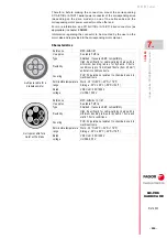
Reference
MPC-1x
S
-
M
e approx.
See table
Type
Shielded. It ensures EMC compatibility.
Flexibility
High. Specifically for cable-carrying chains with a
minimum bending radius for dynamic 7.5x
e and
static 3x
e conditions.
Covering
PUR. Polyurethane resistant to chemicals used in
machines/tools.
Permissible temperature
range
Work: -5°C/+90°C (+23°F/+194°F)
Storage: -40°C/+90°C (-40°F/+194°F)
Rated
voltage
VDE Uo/U: 600/1000 V
UL/CSA 600 V
single-pole cable
Summary of Contents for QC-PDS
Page 1: ...DRIVE QC PDS Hardware manual Ref 2003...
Page 6: ...6 I 6 Ref 2003 6 QC PDS HARDWARE This page intentionally left blank...
Page 16: ...16 Ref 2003 16 Previous I QC PDS HARDWARE This page intentionally left blank...
Page 18: ...18 Ref 2003 18 Previous II QC PDS HARDWARE This page intentionally left blank...
Page 80: ...2 POWER SUPPLIES Power supplies 80 Ref 2003 QC PDS HARDWARE...
Page 138: ...3 DRIVES Drives 138 Ref 2003 QC PDS HARDWARE...
Page 174: ...4 AUXILIARY MODULES Auxiliary modules Ref 2003 174 QC PDS HARDWARE...
Page 302: ...8 INSTALLATION Installation Ref 2003 302 QC PDS HARDWARE...
Page 366: ...12 COMMERCIAL MODELS Commercial models Ref 2003 QC PDS HARDWARE 366...
Page 367: ...ANNEXES...
Page 368: ...ANNEX A1...
Page 383: ...ANNEX A2...
Page 398: ...ANNEX A3...
Page 418: ......
Page 419: ......


