Installation
INSTAL
LAT
ION
System installation
8.
Ref.2003
· 247 ·
QC-PDS
HARDWARE
Electrical installation
Read section
·
in detail and run the cables using
the connectors provided as accessories before carrying out the electrical
connections.
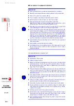
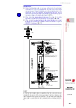
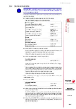
Follow the steps below to perform the complete electrical installation of the
QC-PDS system:
A19 and A19/X11.
Power input to the main power supplies.
A20. Power input to the auxiliary power supply
already integrated in QC-PS-025 power supplies, or external QC-APS-
15 with QC-PS-045 power supplies or exterior QC-APS3-15 with QC-
RPS-
-
power supplies.
X11A and A19/X11 output to feed axis servomotor or spindle motor.
For single drives and regenerative power supplies.
X11A, X11B. Power output to brakeless feed axis servomotors. For all
dual-drives.
X12. Holding brake.
For all single and dual-drives.
X12. KM1 external power contactor control.
For all regenerative power supplies.
X1. Internal communication bus.
Only for the QC-DR-275-
S
S2 drive and QC-RPS-160-
S
N0 power
supply
Connection of braking resistors.
Only for QC-PS-
non-regenerative power supplies and for the QC-
BPM-100 module.
E21A. Motor feedback
For single drives with SERCOS-III interface
E21. Motor feedback.
Only for the QC-DR-275-
S
S2 drive
E21B. Direct feedback.
For single drives with a SERCOS-III interface
E21D. Direct feedback.
Only for the QC-DR-275-
S
S2 drive
E21A/E21B. Motor feedback for each axis.
For dual-drives.
E21A/E21B. Two direct feedback inputs.
For regenerative power supplies.
X6 and node selector (NODE).
Only for QC-DR-275-
S
S2 drive and QC-RPS-160-
S
N0 power supply.
B10A/B10B.
For regenerative power supplies, single and dual drives with a
SERCOS-III interface.
INFORMATION.
In order for FAGOR QC-PDS system to meet the
European Directive on Electromagnetic Compatibility 2014/30/EC, the rules
on equipment installation must be strictly followed regarding:
Mounting of the mains filter, if applicable
Electrical installation of the power part: cable to mains and motor-drive
power connection.
i
INFORMATION.
FAGOR provides all the cables needed for the installation.
If the user chooses to make a cable, refer to chapter
, which
indicates the pinout of the connectors at both ends, mechanical
characteristics and other considerations.
i
Summary of Contents for QC-PDS
Page 1: ...DRIVE QC PDS Hardware manual Ref 2003...
Page 6: ...6 I 6 Ref 2003 6 QC PDS HARDWARE This page intentionally left blank...
Page 16: ...16 Ref 2003 16 Previous I QC PDS HARDWARE This page intentionally left blank...
Page 18: ...18 Ref 2003 18 Previous II QC PDS HARDWARE This page intentionally left blank...
Page 80: ...2 POWER SUPPLIES Power supplies 80 Ref 2003 QC PDS HARDWARE...
Page 138: ...3 DRIVES Drives 138 Ref 2003 QC PDS HARDWARE...
Page 174: ...4 AUXILIARY MODULES Auxiliary modules Ref 2003 174 QC PDS HARDWARE...
Page 302: ...8 INSTALLATION Installation Ref 2003 302 QC PDS HARDWARE...
Page 366: ...12 COMMERCIAL MODELS Commercial models Ref 2003 QC PDS HARDWARE 366...
Page 367: ...ANNEXES...
Page 368: ...ANNEX A1...
Page 383: ...ANNEX A2...
Page 398: ...ANNEX A3...
Page 418: ......
Page 419: ......


