Installation
8.
INSTAL
LAT
ION
System installation
302
Ref.2003
· 250 ·
QC-PDS
HARDWARE
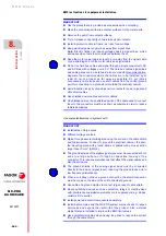
Before handling the terminals, proceed as indicated and in the following
order:
With respect to the safety functions, keep in mind that:
WARNING
.
Disconnect the mains voltage at the electrical cabinet.
Wait a few minutes before handling these terminals.
The power supply of the main QC-PDS system requires time to decrease
the voltage of the power bus to safe values (< 60 V DC or 42.4 Vpeak). The
green indicator DC BUS ON being turned OFF does not mean that the
power bus may be handled or manipulated. The discharge time
depends on
the number of elements connected and it is about 10 minutes.
In screw tightening connections, rigorously apply the torque values shown in
this manual for connectors.
Check if the connectors with automatic locking or a locking lever perform
their function satisfactorily.
Mark these checks in the maintenance plan.
WARNING.
The
STO
·
S
afe
T
orque
O
ff
·
and/or
SBC
·
S
afe
B
rake
C
ontrol
·
safety functions do not result in an electrical disconnection. The DC BUS
remains under low voltage. Ignoring this warning may cause electrical
shock.
Summary of Contents for QC-PDS
Page 1: ...DRIVE QC PDS Hardware manual Ref 2003...
Page 6: ...6 I 6 Ref 2003 6 QC PDS HARDWARE This page intentionally left blank...
Page 16: ...16 Ref 2003 16 Previous I QC PDS HARDWARE This page intentionally left blank...
Page 18: ...18 Ref 2003 18 Previous II QC PDS HARDWARE This page intentionally left blank...
Page 80: ...2 POWER SUPPLIES Power supplies 80 Ref 2003 QC PDS HARDWARE...
Page 138: ...3 DRIVES Drives 138 Ref 2003 QC PDS HARDWARE...
Page 174: ...4 AUXILIARY MODULES Auxiliary modules Ref 2003 174 QC PDS HARDWARE...
Page 302: ...8 INSTALLATION Installation Ref 2003 302 QC PDS HARDWARE...
Page 366: ...12 COMMERCIAL MODELS Commercial models Ref 2003 QC PDS HARDWARE 366...
Page 367: ...ANNEXES...
Page 368: ...ANNEX A1...
Page 383: ...ANNEX A2...
Page 398: ...ANNEX A3...
Page 418: ......
Page 419: ......


