Installation
8.
INSTAL
LAT
ION
Ele
ctrica
l co
nne
ctio
ns
302
Ref.2003
· 278 ·
QC-PDS
HARDWARE
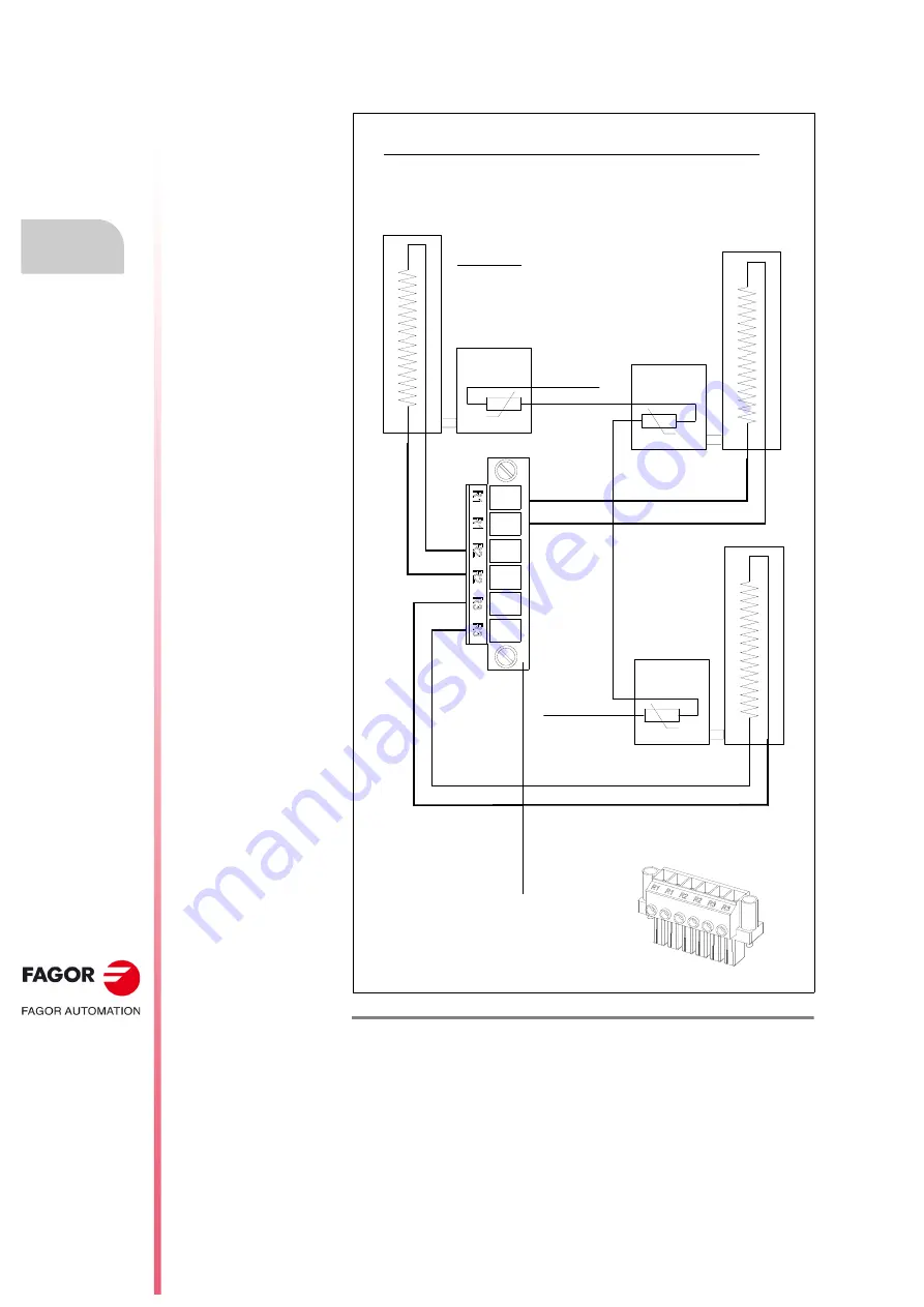
How to install THREE ER+TH-18/1100 resistors in parallel to
the QC-BPM-100 module
F. H8/32
QC-BPM-100. The connection of THREE external braking resistors in parallel.
+24 V DC
200°C
R
R
R
R
200°C
R
R
200°C
EXTERNAL
THERMOSTAT
EXTERNAL
THERMOSTAT
EXTERNAL
THERMOSTAT
PLC INPUT
Always install the resistors vertically
Diagram for 3 resistors in parallel with an external thermostat
Connect according to the figure the
terminal labeled
+24 V DC
to an external
24 V DC power supply of the electrical
cabinet and the
PLC INPUT
to a PLC
input.
Important. Remember to manage the
chosen PLC input in the PLC program to
generate an error when exceeding the limit
temperature (200 °C) detected by the
sensor and to open the contact.
ER-
T
H-
18
/110
0
ER
-T
H
-18
/1
10
0
ER-
T
H-
18
/110
0
X56 connectors to connect the
external braking resistors to the
QC-BPM-100 module
X56
Summary of Contents for QC-PDS
Page 1: ...DRIVE QC PDS Hardware manual Ref 2003...
Page 6: ...6 I 6 Ref 2003 6 QC PDS HARDWARE This page intentionally left blank...
Page 16: ...16 Ref 2003 16 Previous I QC PDS HARDWARE This page intentionally left blank...
Page 18: ...18 Ref 2003 18 Previous II QC PDS HARDWARE This page intentionally left blank...
Page 80: ...2 POWER SUPPLIES Power supplies 80 Ref 2003 QC PDS HARDWARE...
Page 138: ...3 DRIVES Drives 138 Ref 2003 QC PDS HARDWARE...
Page 174: ...4 AUXILIARY MODULES Auxiliary modules Ref 2003 174 QC PDS HARDWARE...
Page 302: ...8 INSTALLATION Installation Ref 2003 302 QC PDS HARDWARE...
Page 366: ...12 COMMERCIAL MODELS Commercial models Ref 2003 QC PDS HARDWARE 366...
Page 367: ...ANNEXES...
Page 368: ...ANNEX A1...
Page 383: ...ANNEX A2...
Page 398: ...ANNEX A3...
Page 418: ......
Page 419: ......


