Installation
8.
INSTAL
LAT
ION
Ele
ctrica
l co
nne
ctio
ns
302
Ref.2003
· 284 ·
QC-PDS
HARDWARE
QC-APS3-15 + QC-RPS-
-F
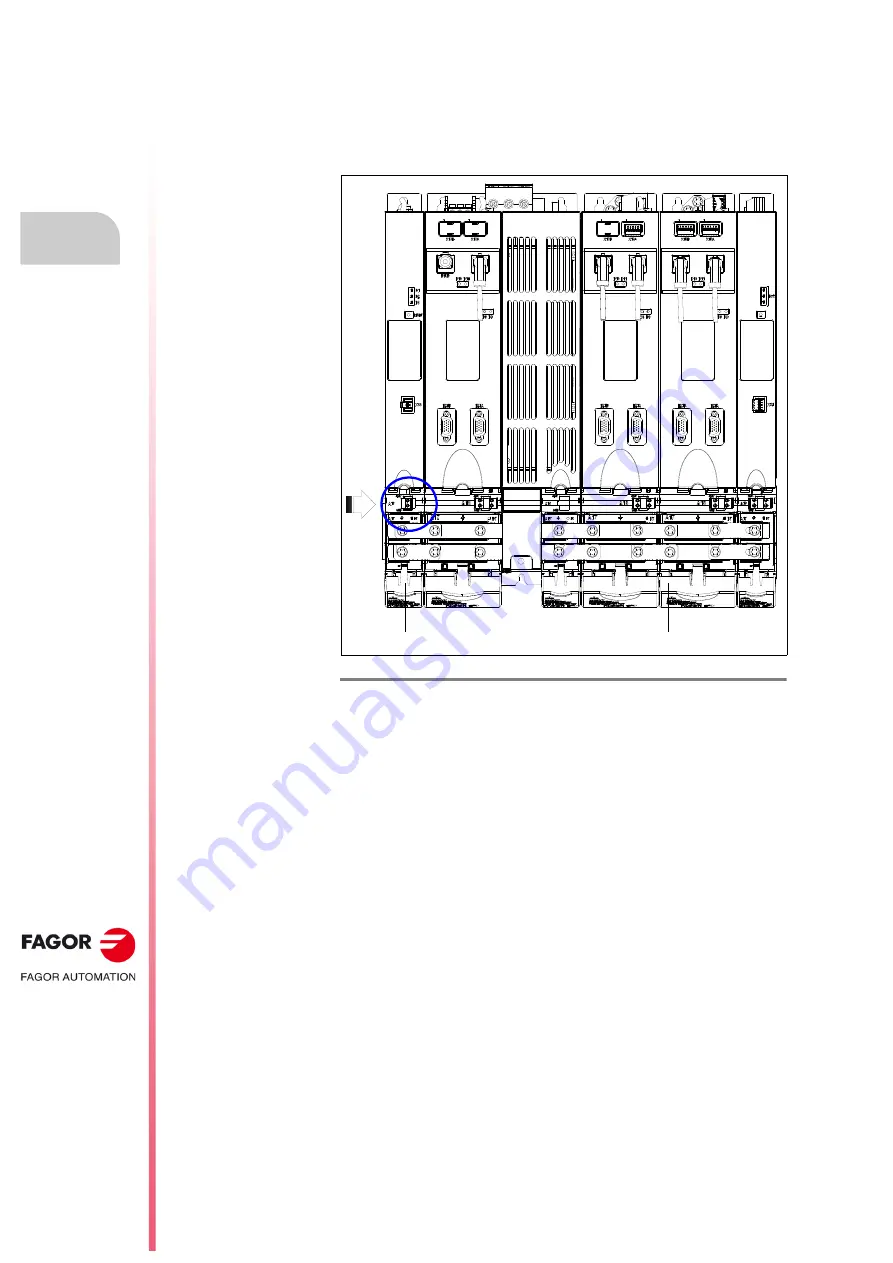
The connection is made using two 2.5 mm² conductors to connect,
respectively, the under cover +24V/GND terminals of the A18 connector of
the QC-APS3-15 auxiliary power supply with the under cover +24V/GND
terminals of the A18 connector of the adjacent QC-RPS-
-F
power
supply. See figure.
All the information regarding the A18 connector is available in the chapter
regarding the applicable module, power supply, drive or auxiliary module.
F. H8/35
Connector A18. +24 V DC output of the QC-APS3-15 auxiliary power supply.
A18
QC-APS3-15
QC-RPS-030-FF2
QC-DR-40-FS2
QC-DR-30+30-FD2
QC-BPM-100
Summary of Contents for QC-PDS
Page 1: ...DRIVE QC PDS Hardware manual Ref 2003...
Page 6: ...6 I 6 Ref 2003 6 QC PDS HARDWARE This page intentionally left blank...
Page 16: ...16 Ref 2003 16 Previous I QC PDS HARDWARE This page intentionally left blank...
Page 18: ...18 Ref 2003 18 Previous II QC PDS HARDWARE This page intentionally left blank...
Page 80: ...2 POWER SUPPLIES Power supplies 80 Ref 2003 QC PDS HARDWARE...
Page 138: ...3 DRIVES Drives 138 Ref 2003 QC PDS HARDWARE...
Page 174: ...4 AUXILIARY MODULES Auxiliary modules Ref 2003 174 QC PDS HARDWARE...
Page 302: ...8 INSTALLATION Installation Ref 2003 302 QC PDS HARDWARE...
Page 366: ...12 COMMERCIAL MODELS Commercial models Ref 2003 QC PDS HARDWARE 366...
Page 367: ...ANNEXES...
Page 368: ...ANNEX A1...
Page 383: ...ANNEX A2...
Page 398: ...ANNEX A3...
Page 418: ......
Page 419: ......


