Installation
8.
INSTAL
LAT
ION
C
onne
cti
on
of the
con
trol
a
nd
communica
tions
signa
ls
302
Ref.2003
· 292 ·
QC-PDS
HARDWARE
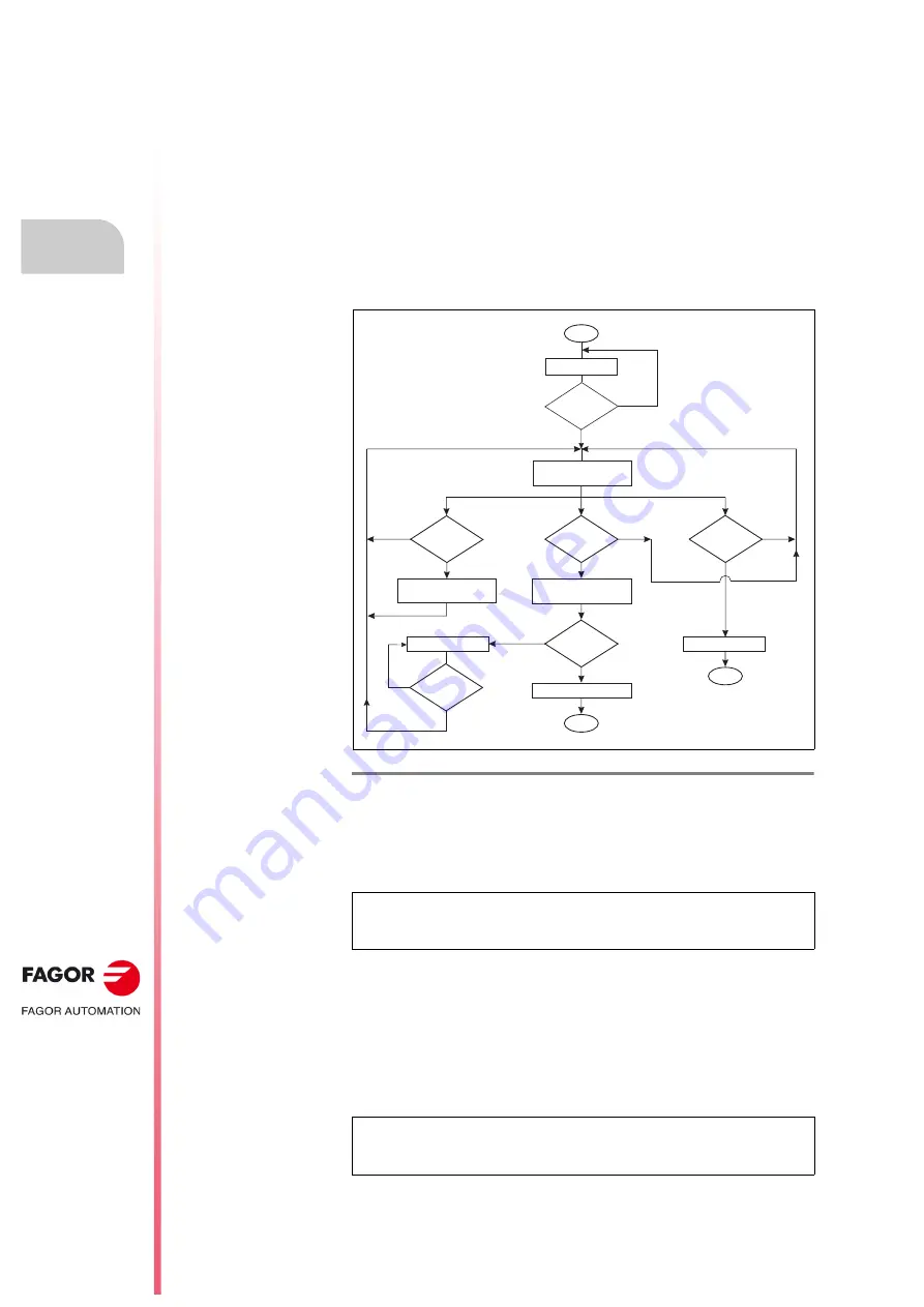
Transmission speed changing procedure
In an initial state (0 state), the display shows the information on the error
codes, SERCOS phase, etc. Keeping the BOOT button pressed for 3
seconds (long push) it switches to a new state (state 1) that is used for
selecting the communication speed and the display shows the speed
currently selected.
In this state 1, every time this button is pressed for less than 0.8 seconds
(short push), the display shows the next communication speed value that
may be selected. Hence, apply several short pushes until the desired
speed is displayed.
Once the display shows the desired speed, apply a long push and a QP11
value will be assigned and it will be saved into the flash memory of the
module where it will also cause the unit to RESET.
Anomalous events during the procedure
Any error that comes up when saving parameters into flash memory will
be displayed with an error message on the display while the BOOT button
is pressed and then it will return to state 1 (speed selection).
Any change made to the communication speed is retained after the module
has been turned off, provided that the command to save parameters has
been previously executed successfully.
If, for any reason, the module is turned off or reset in any stage of this
procedure, when started up again, the transmission speed value given by
QP11 will be the last one that was successfully assigned during previous
changes. The speed change procedure may be ignored (without making
any changes) at any time if the command to save parameters has not been
executed.
Refer to the values that can be assigned to parameter QP11 in chapter 13
of the
·
man_dds_soft.pdf
·
manual.
F. H8/42
Diagram of the SERCOS-II transmission speed selecting procedure.
NOTE.
Any attempt to select a value other than those assigned to the
possible transmission speeds will generate an error and it will not be
selected.
NOTE.
While in state 1, and after 8 seconds without pressing the “BOOT”
button, the module switches to state 0 and the display will show the initial
information.
NO
YES
YES
NO
NO
NO
YES
NORMAL DISPLAY
Start
Button
ON
t > 3 s
YES
SHOW the transmission
rate on the DISPLAY
Pressed
t < 0.8 s
Button
ON
t > 3 s
Button
OFF
t > 3 s
SAVE PARAMETERS
Drive RESET
ERROR MESSAGE
NO
NO
YES
Button
OFF
END
NEXT RATE
NORMAL DISPLAY
END
SAVED
OK
YES
Summary of Contents for QC-PDS
Page 1: ...DRIVE QC PDS Hardware manual Ref 2003...
Page 6: ...6 I 6 Ref 2003 6 QC PDS HARDWARE This page intentionally left blank...
Page 16: ...16 Ref 2003 16 Previous I QC PDS HARDWARE This page intentionally left blank...
Page 18: ...18 Ref 2003 18 Previous II QC PDS HARDWARE This page intentionally left blank...
Page 80: ...2 POWER SUPPLIES Power supplies 80 Ref 2003 QC PDS HARDWARE...
Page 138: ...3 DRIVES Drives 138 Ref 2003 QC PDS HARDWARE...
Page 174: ...4 AUXILIARY MODULES Auxiliary modules Ref 2003 174 QC PDS HARDWARE...
Page 302: ...8 INSTALLATION Installation Ref 2003 302 QC PDS HARDWARE...
Page 366: ...12 COMMERCIAL MODELS Commercial models Ref 2003 QC PDS HARDWARE 366...
Page 367: ...ANNEXES...
Page 368: ...ANNEX A1...
Page 383: ...ANNEX A2...
Page 398: ...ANNEX A3...
Page 418: ......
Page 419: ......


