Power supplies
80
2.
POWER SUPPLIES
Rege
nerative
Pow
er Su
ppli
es
· 64 ·
Ref.2003
· 64 ·
QC-PDS
HARDWARE
Function
A19/X11 connector.
Power input to the main power supply
QC-RPS-030-F
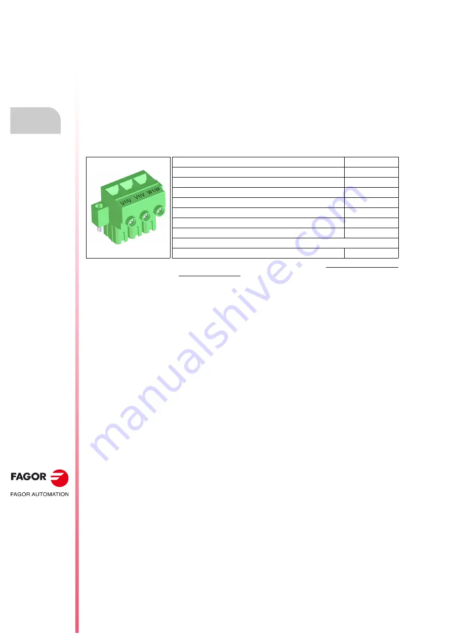
Male 3-pin connector located on top of the drive and identified as A19/X11.
The female aerial plug connector with screw connection with tension sleeve
(labeled as U1/U, V1/V, W1/W) is supplied as an accessory. It is used to
connect the main power supply to the three-phase mains via the RPS-45
CHOKE.
The following table shows the main data of the aerial plug-in connector and
the wire to be connected:
Pinout
The pinout is printed on the connector as U1/U-V1/V-W1/W.
Installation
See section,
8.5.1 CONNECTING THE MAIN POWER SUPPLY TO THE MAINS
Connector data
QC-RPS-030
Nr of poles
3
Gap (mm)
15
Torx screwdriver, size (mm)
TX 20x80
Min./max. admissible cross-section (mm²)
16/35
Max. rated current (A):
48
Cross-section S (mm²) for max. rated current
*
16
Tightening torque (N·m)
2.5
Connection data
Length to strip (mm)
20
*
Compliant with EN 60204-1, table 6 - method B2. The recommended cross-
section can be smaller depending on the rated power demanded from the power
Summary of Contents for QC-PDS
Page 1: ...DRIVE QC PDS Hardware manual Ref 2003...
Page 6: ...6 I 6 Ref 2003 6 QC PDS HARDWARE This page intentionally left blank...
Page 16: ...16 Ref 2003 16 Previous I QC PDS HARDWARE This page intentionally left blank...
Page 18: ...18 Ref 2003 18 Previous II QC PDS HARDWARE This page intentionally left blank...
Page 80: ...2 POWER SUPPLIES Power supplies 80 Ref 2003 QC PDS HARDWARE...
Page 138: ...3 DRIVES Drives 138 Ref 2003 QC PDS HARDWARE...
Page 174: ...4 AUXILIARY MODULES Auxiliary modules Ref 2003 174 QC PDS HARDWARE...
Page 302: ...8 INSTALLATION Installation Ref 2003 302 QC PDS HARDWARE...
Page 366: ...12 COMMERCIAL MODELS Commercial models Ref 2003 QC PDS HARDWARE 366...
Page 367: ...ANNEXES...
Page 368: ...ANNEX A1...
Page 383: ...ANNEX A2...
Page 398: ...ANNEX A3...
Page 418: ......
Page 419: ......


