background image


9    


fagorindustrial.com


3.3 

 Machine settings and programs 

Changing the Set Point of the temperature on the controller 

The  unit  comes  with  a  factory  default  set  point  (  32°F  Refrigerators).  These  set 
values  will  make  the  unit  perform  at  its  maximum  capacity.  Therefore,  it  is  not 
recommended to change the set point. If set point needs to be changed, follow the 
next steps.  

1.


Push the SET button for one second. You should see a flashing number. 
Release the button. 


2.


Press  the  up  and  down  arrows  to  increase  or  decrease  the  set 
temperature. Then press the set button to save the new set point. 


Note: 

The  maximum  value  you  can  set  in  the  controller  is:  For  refrigerators:  5°C 
(40°F) 

3.


If  you  wish  decrease  the  value  of  the  set  point  for  a  new  temperature, 
press the button DOWN arrow (see the picture below). Press this button 
to  reach  the desired  value.  Release  the  button  and  then  press  the SET 
button to keep, and save, the new value. 

Note:  

The minimum  value you  can  set  in  the  controller  is:  For  refrigerators:  -1°C 
(30°F) 

Manual Defrost 

To select manual defrost, hold the button DOWN arrow for 5 seconds. The snow 
flake icon will appear on the display. When this icon is solid it indicates that the 
equipment is in Defrost mode. 


To  exit  manual  defrost,  hold  the  DOWN  button  arrow  for  5  seconds.  The  snow 
flake icon will turn off. Wait 2 minutes for the compressor to start 


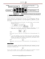
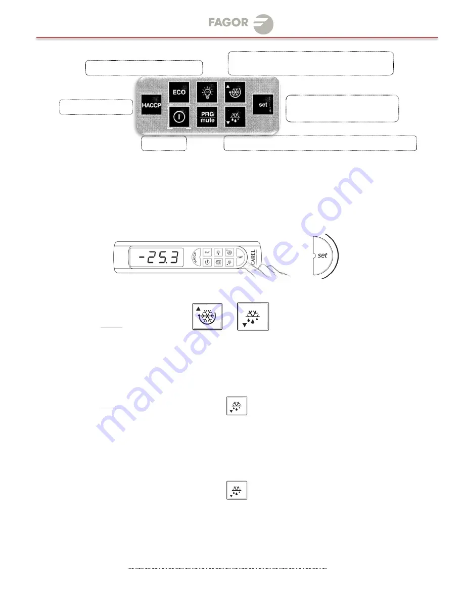
FIGURE 1 


ALARM MENU 

ON/OFF 


ENERGETIC  SAFETY MODE 


To increase Set Point of Temperature 
/Continues cycle 

To Change the set point 
To access programming mode 

To decrease Set Point of Temperature To set a manual defrost 

Summary of Contents for QVR-1 N

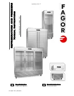
Page 1: ...MARCH 2017 REFRIGERATORS AND FREEZERS Manual Instructions PREMIUM LINE N Manual instructions Installation and Operation Manual de instrucciones Uso y mantenimiento ES EN DOCUMENT CODE 602305M0063...

Page 2: ...identification label description 7 2 5 Installation and assembly 8 2 6 Connections electrical 8 OPERATION 8 3 1 General information 8 3 2 Control panel description 8 3 2 1 Electronic Control 8 3 3 Ma...

Page 3: ...stalaci n y Ensamble 16 2 6 Conexiones 16 OPERACION 16 3 1 Informaci n General 16 3 2 Descripci n del panel de control 16 3 2 1 Control electronico 16 3 3 Configuraciones del Equipo 17 4 1 Reglas de s...

Page 4: ...___________________________ MODEL HP DIMENSIONS in mm VOLTAGE V AMP A REFRIGERANT CHARGE TIPO REFRIG BTUS HR WEIGHT LB QVR 1 N 1 4 17 x 31 x 80 685 x 675 x 1825 115 220 5 0 3 1 11 3 Oz R 134a 1660 264...

Page 5: ...eaning the condensing unit If machine still running when power is off disconnect power at the circuit breaker before unplugging the machine WARNING Machine and compressor warranties are void if failur...

Page 6: ...that may have occurred during transportation Visually inspect the exterior of the package if damaged open and inspect the contents with the carrier Any damage should be noted and reported on the deliv...

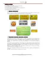
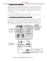
Page 7: ...tandards If you want know more about other restrictions about your equipment see the warranty that is located in the final part of your manual 2 4 Manufacturer s identification label description The d...

Page 8: ...onnected to the proper power source Verify correct incoming voltage according to the Data Plate information The data plate in located inside the unit near the top front left corner Under any circumsta...

Page 9: ...decrease the value of the set point for a new temperature press the button DOWN arrow see the picture below Press this button to reach the desired value Release the button and then press the SET butt...

Page 10: ...other vegetables 4 2 1 Cleaning the Condenser Coil Disconnect machine Remove front bottom panel and carefully slide out the condensing unit The condenser coil requires regular cleaning recommended ev...

Page 11: ...d from moving or bumping the drain IF YOU NOTICE EXCESSIVE WATER ACCUMULATION ON THE INSIDE OF THE UNIT be sure the drain tube is connected from the evaporator housing to the condensate evaporator dra...

Page 12: ...insure proper air flow product must not be placed higher than the maximum level mark located on the internal wall of the unit g If FREEZER check that the temperature is not Celsius h Check that the ga...

Page 13: ...ar el mantenimiento reparaci n o limpieza de la unidad condensadora Si la m quina sigue funcionando cuando est apagado desconecte la alimentaci n principal antes de desenchufar la m quina La garant a...

Page 14: ...abra e inspeccione delante de la empresa transportadora todo el equipo Cualquier da o debe ser anotado y reportado en el recibo de entrega de la empresa transportadora IMPORTANTE Una vez que se haya r...

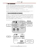
Page 15: ...es relacionadas con el equipo ver la garant a que se encuentra localizada al final del manual 2 4 Placa de identificaci n del Fabricante La placa de datos se encuentra dentro del gabinete cerca de la...

Page 16: ...Conexiones Tome en cuenta los datos sobre el amperaje y voltaje que aparecen en la placa matricula del equipo Es indispensable que la instalaci n el ctrica del usuario cumpla con los requerimientos y...

Page 17: ...evo valor Nota El valor maximo que el control puede mostrar es en refrigeradores 5 C 40 F 3 Si desea disminuir el valor del SET POINT para una nueva temperatura presione el bot n de flecha hacia abajo...

Page 18: ...tos alimenticios de cualquier superficie de acero inoxidable 4 2 1 Limpiando el condensador Desconecte la m quina Quite el panel delantero inferior y cuidadosamente Deslice hacia afuera la unidad cond...

Page 19: ...evaporador Cada drenaje puede ser removido o desconectado Si percibe excesiva acumulaci n de agua en el interior de la unidad aseg rese de que est conectado el tubo de desag e del evaporador a la band...

Page 20: ...ontrol no marque alguna alarma d Verifique que el SET POIT de temperatura es el correcto e Verifique que no existe obstrucci n al flujo del aire en el interior del equipo f Verifique que el ventilador...

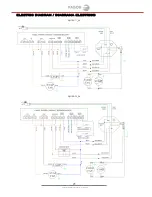
Page 21: ...21 fagorindustrial com ELECTRIC DIAGRAM DIAGRAMA ELECTRICO QVR 1_N QVR 2_N...

Page 22: ...22 fagorindustrial com QVR 3_N QVF 1_N...

Page 23: ...23 fagorindustrial com QVF 2_N QVF 3_N...

Page 24: ...24 fagorindustrial com ANEXOS...

Page 25: ...25 fagorindustrial com...

Page 26: ...e Industrial Tres Naciones San Lu s Potos S L P M xico Tel fono Planta S L P 52 444 137 0500 Ext 538 Sin costo 01 800 00 FAGOR MULTI SOLUTION MANUFACTURER OF FOODSERVICE EQUIPMENT 13105 NW 47th Ave Mi...

Reviews: