background image

- 9 -

GB

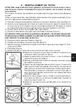
9 -  REPLACEMENT OF THE HOSE

WARNING: BEFORE PERFORMING ANY OPERATION, POSITION THE STOPPER AT 

THE END OF THE HOSE, REEL THE HOSE COMPLETELY AND MAKE SURE THAT THE 

SPRING IS COMPLETELY SLACKENED.

For safety reasons, operations of hose replacement must be carried out at the bench.

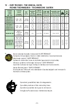
Use a hose with dimension and pressure characteristics suited to the use (see table of cha

-

racteristics page 22).

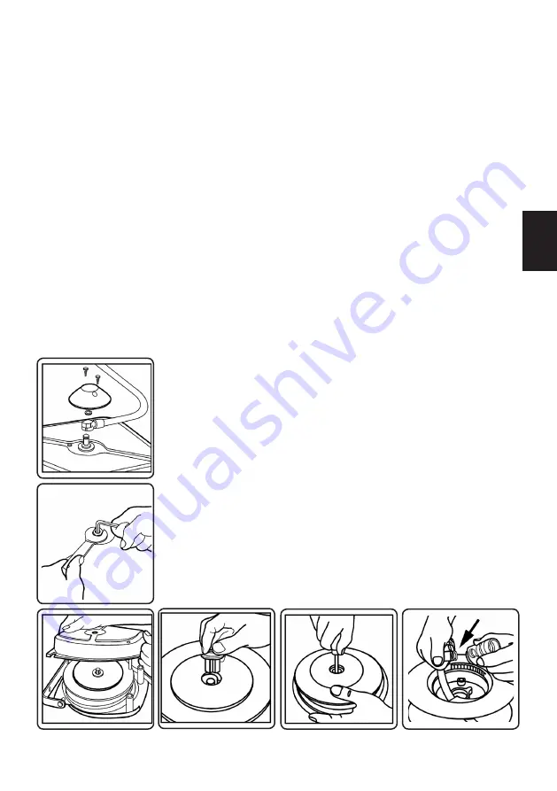
1)  Take the inlet hose off by removing the plastic cap and the seeger (figure A).

2)  Insert a 5 mm hexagonal wrench into the axle of the spring linkage shaft. Unfasten the 

nut with a 19 mm wrench, holding in place with the hexagonal wrench (figure B). Release 

the spring by turning the hexagonal wrench slowly clockwise.

3)  Remove the nut and the 4 attachment screws from the two half-casings.

4)  Remove the half-casing and take out the drum (figure C).

WARNING: DO NOT OPEN THE SPRING CASING. SPRING REPAIR OR REPLACEMENT 

OPERATIONS MUST ONLY BE PERFORMED BY QUALIFIED TECHNICIANS.

5)  Take the spring hub out of the drum (figure D).

6)  Unfasten the central screw and remove the bushing (figure E).

7)  Separate the hub from the drum and take the hose coupling out of the hub (figure F). 

Remove the o-ring.

8)  Replace the hose.

9)  Position the o-ring on the coupling and insert the coupling into the hub hole.

A

B

C

D

E

F

10) Reposition the hub in the drum by fastening the central screw 

and insert the spring hub.

11) Fit  the  stop  approximately  1  m  from  the  opposite  end  of  the 

hose and reel the new hose on the drum.

12) Grease if required. Reassemble the reel, following the opera-

tions in reverse order.

13) Insert the hex wrench into the axle after the side bodies have 

been  attached. Turn  the  wrench  anti-clockwise  and  bring  the 

hose rubber stop into contact with the roller support. Pre-load 

the  spring  while  continuing  to  turn  anti-clockwise  the  wrench 

(see table of technical data page 22).

14) Hold the wrench in position and fasten the nut. Perform a fun-

ctional check. If the hose does not go in completely or does not 

come out completely, readjust the tension of the spring 

  (point 13).

15) Reposition the inlet hose and the plastic cap.

Summary of Contents for MNP

Page 1: ...CI ENROULEURS AUTOMATIQUES AUTOMATISCHE SCHLAUCHAUFROLLER AUTOMATIC HOSE REELS MANUALE USO E MANUTENZIONE USE AND MAINTENANCE MANUAL NOTICE D UTILISATION ET D ENTRETIEN GEBRAUCHSANWEISUNG 20 MGP MNP M...

Page 2: ...NATION DU MATERIEL POLLUE page 14 11 DECLARATION DE CONFORMITE CE page 14 Annexes 12 PIECES DETACHEES page 20 13 FICHES TECHNIQUES page 22 1 GENERAL RULES APPLIED page 7 2 WARRANTY page 7 3 DESCRIPTIO...

Page 3: ...per il funzionamento di errata installazione o manutenzione di manutenzioni operate da personale non autorizzato di danni da trasporto ovvero di circostanze che comunque non si possono far risalire a...

Page 4: ...della ditta costruttrice finale e il simbolo CE tutte le notizie necessarie alla chiara identificazione della macchina modello utilizzo numero di serie peso ecc 1059 5 kg MNP200812 HOSE REEL for AIR 2...

Page 5: ...TA O SOSTITUITA SOLO DA TECNICI ABILITATI 5 Estrarre il mozzo attacco molla dal tamburo figura D 6 Smontare la vite centrale e la boccola figura E 7 Separare il mozzo dal tamburo ed estrarre il raccor...

Page 6: ...pedire il raggiungimento di zone pericolose con gli arti superiori e inferiori La persona autorizzata a costituire il fascicolo tecnico il Sig Torino Renato in qualit di titolare dell azienda 10 SMALT...

Page 7: ...els models MNP MGP are made of hot galvanized moulded steel and painted with electrostatic polyester powder system in order to guarantee a long life of the product The incorporated revolving support a...

Page 8: ...ple or da mages to things caused by a wrong assembly of the hose reel IMPORTANT Any installation operation shall be carried out by a suitably trained staff following carefully the information given in...

Page 9: ...TECHNICIANS 5 Take the spring hub out of the drum figure D 6 Unfasten the central screw and remove the bushing figure E 7 Separate the hub from the drum and take the hose coupling out of the hub figu...

Page 10: ...disposal of industrial waste The manufacturer TORINO RENATO COSTRUZIONI MECCANICHE Via Antica di Cuneo 43 12022 Busca CN Italy Tel 39 0171 937152 Fax 39 0171 937302 info faicomitaly com www faicomital...

Page 11: ...r selon la direction d utilisation du tuyau Les appareils enroulent automatiquement le tuyau par un ressort en acier de haute qualit in corpor dans le tambour et permettent de l arr ter la longueur so...

Page 12: ...de l enrouleur IMPORTANT Les op rations d installations doivent tre effectu es par des techniciens op portun ment entra n s suivant les instructions donn es sur ce manuel 1059 5 kg MNP200812 HOSE REE...

Page 13: ...RE EFFECTUEES QUE PAR DES TECHNICIENS HABILITES 5 Extraire le moyeu ressort du tambour figure D 6 D visser la vis centrale et enlever la douille figure E 7 S parer le moyeu du tambour et extraire le r...

Page 14: ...cialis es dans l limination des d chets industriels Le fabricant TORINO RENATO COSTRUZIONI MECCANICHE Via Antica di Cuneo 43 12022 Busca CN Italy Tel 39 0171 937152 Fax 39 0171 937302 info faicomital...

Page 15: ...ers f r Missbrauch bei Montage Gebrauch und Wartung des Ger ts Um eine lange Lebensdauer zu gew hrleisten sind die Schlauchaufroller Modell MNP MGP aus hei verzinktem formgepresstem Stahlblech gebaut...

Page 16: ...kundigen Person ausgef hrt werden und unter Befolgung der in diesem Handbuch angegebenen Hin weise 1059 5 kg MNP200812 HOSE REEL for AIR 20 bar 8x12 12 m TORINO RENATO BUSCA CUNEO ITALY 8 WARTUNG Sich...

Page 17: ...eder aus der Trommel entnehmen Abb D 6 Die Mittelschraube l sen und die H lse entnehmen Abb E 7 Die Nabe aus der Trommel entnehmen und die Kupplung aus dem Schlauch herausne hmen Abb F Die O Ring Dich...

Page 18: ...an Fachbetrieben f r die Entsorgung von Industrieabf llen zuzuf hren Der Hersteller TORINO RENATO COSTRUZIONI MECCANICHE Via Antica di Cuneo 43 12022 Busca Cuneo Italy Tel 39 0171 937152 Fax 39 0171 9...

Page 19: ...19 ALLEGATI PARTI DI RICAMBIO DATI TECNICI ENCLOSURES SPARE PARTS TECHNICAL DATA ANNEXES PIECES DETACHEES FICHES TECHNIQUES BEILAGE ERSATZTEILE TECHNISCHE DATEN...

Page 20: ...0 0456 0455 MFSG12 0253 0452 0453 0445 0345 0096 0493 0502 0313 0127 8 0022A1 10 0313 0388 0474 0448 0449 0454 0018 0409 0468 0501 0471 0331 0299 0297 0130 0446 0465 8 0447 0466 10 0333 0499 0450 0451...

Page 21: ...URSE JAUNE VIS TC 5x12 VIS TE 6x21 HILO RESSORT DE CLIQUET PIVOT DE CLIQUET ETRIER DEMISUPPORT SUPERIEUR mod MNP DEMISUPPORT INFERIEUR mod MNP VIS TC 5x16 HILO ECROU M 12 CLIQUET VIS TC M 4x10 RACCORD...

Page 22: ...I 8 G 1 4 M PU 8x12 15 m 50 ft 6 7 4 5 MGPX200815 MGPX201012 MGPSX200815 MGPSX201012 ARIA AIR AIR LUFT ACQUA WATER EAU WASSER DETERGENTE DETERGENT D TERGENT WASCHMITTEL T 70 C 20 Bar 280 PSI 8 10 8 10...

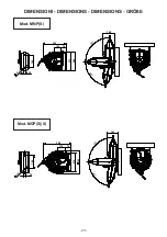
Page 23: ...23 103 74 345 288 272 30 1 0 5 190 165 90 8 0 115 74 392 272 324 190 1 0 5 30 90 165 8 0 DIMENSIONI DIMENSIONS DIMENSIONS GR E Mod MGP S X Mod MNP S...

Page 24: ...71 937302 info faicomitaly com www faicomitaly com Obbligo di conservazione del manuale E fatto obbligo di conservare codesto manuale in un luogo facilmente accessibile a disposizione di tutti gli ope...

Reviews: