background image

HCPL-3700  A

C/DC to Logic Interface Optocoupler

©2005 Fairchild Semiconductor Corporation

www.fairchildsemi.com

HCPL-3700 Rev. 1.0.1

7


5

6

7

8

3

4

2

1

Z  = 50

tr = 5ns

Generator

Pulse

O

.1uf
bypass

O

(V  )

+5V

R

L

Output

PHL

t

PLH

t

5V

2.5V

IN

(V  ) 

Input

(V  )

Output

O

1.5 V

90%

AC

DC+

DC-

AC

GND

V

V

O

CC

AC

DC-

DC+

AC

4

3

2

1

Output

O

GND

V

5

6

(V  )

R

bypass

.1uf

CC

V

7

8

L

O

V

FF

I

IN

A

B

+5V

C **

L

* SEE NOTE 8

R  *

CC

+

Pulse Gen

CM

V

-

** C  IS 30 pF, WHICH INCLUDES PROBE

AND STRAY WIRING CAPACITANCE

L

90%

10%

10%

r

t

t

f

0V

V  

O

OL

V  

Switching Pos. (A)

 I    = 0 mA

V

O

V

CM

Switching Pos. (B) 

I    = 3.11 mA 

V   (Max)

V   (Min)

O

O

IN

IN

CM

L

H

O

V

V

OL

CM

V

V

CM

L

H

CM

5V

5V

V
Pulse Amplitude = 50 V
Pulse Width = 1 ms
f = 100 Hz
T  = T  = 1.0 

µ

s (10 - 90%)

IN

r

f

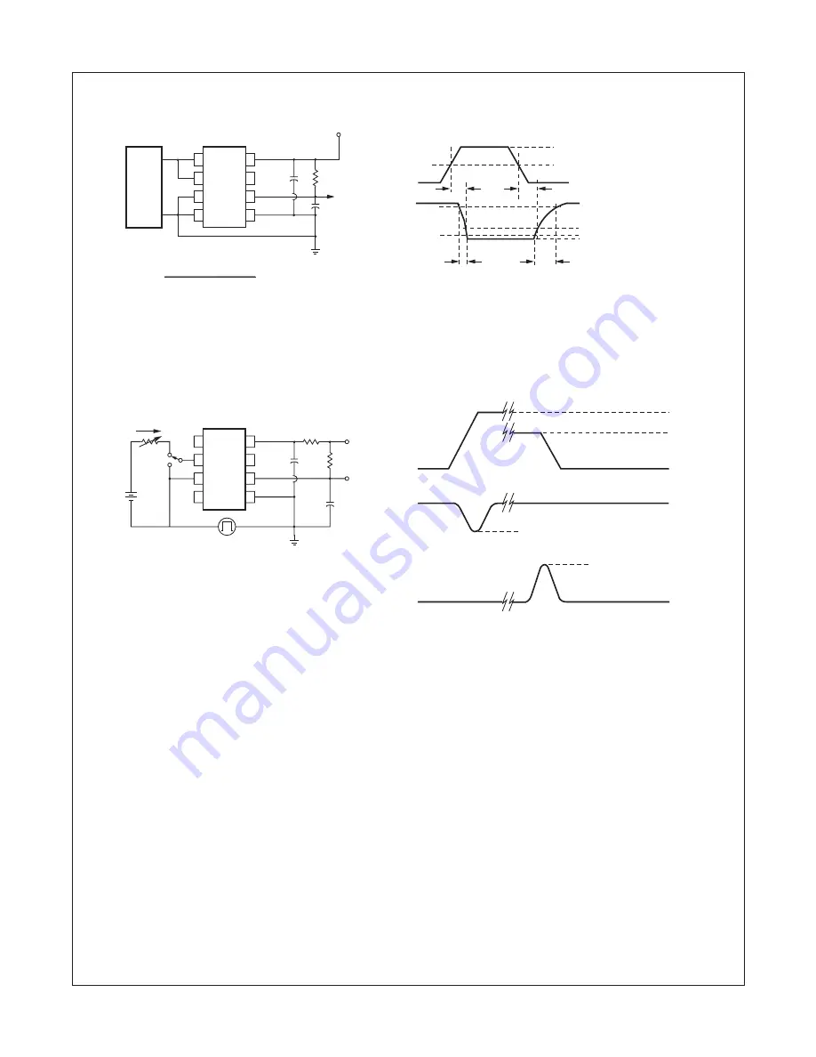
Fig. 9. Switching Test Circuit

Fig. 10. Test Circuit for Common Mode Transient Immunity and Typical Waveforms

Summary of Contents for AC/DC to Logic Interface Optocoupler...

Page 1: ...oltage sensing Relay contact monitor Current sensing Microprocessor Interface Industrial controls Description The HCPL 3700 voltage current threshold detection optocoupler consists of an AlGaAs LED co...

Page 2: ...mperature at a rate of 1 9 mW C Recommended Operating Conditions The Recommended Operating Conditions table defines the conditions for actual device operation Recommended operating conditions are spec...

Page 3: ...2 01 2 5 2 86 V VTH AC Pins 1 4 VIN V1 V4 Pins 2 3 Open VCC 4 5 V VO 0 4 V 5 IO 4 2 mA 4 23 5 0 5 50 V VTH VIN V1 V4 Pins 2 3 Open VCC 4 5 V VO 2 4 V 5 IO 100 A 2 87 3 7 4 20 V IHYS Hysteresis IHYS IT...

Page 4: ...d be included to protect the detector chip from destructive surge currents The recommended value for RCC is 240V per volt of allowable drop in VCC between pin 8 and VCC with a minimum value of 240 9 D...

Page 5: ...ure TA TEMPERATURE C 40 20 0 25 45 65 85 Input Current I IN mA 1 8 2 0 2 2 2 4 2 6 2 8 3 0 3 2 3 4 3 6 3 8 4 0 4 2 V OL mV 0 10 20 30 40 50 60 70 80 90 100 110 120 Fig 4 Current Threshold Voltage Thre...

Page 6: ...ernal Threshold Characteristics V V vs Rx RX EXTERNAL SERIES RESISTOR K 0 40 80 120 160 200 240 V V EXTERNAL THRESHOLD VOLTAGE V 0 50 100 150 200 250 300 Fig 7 Logic High Supply Current vs Temperature...

Page 7: ...AC 4 3 2 1 Output O GND V 5 6 V R bypass 1uf CC V 7 8 L O VFF IIN A B 5V C L SEE NOTE 8 R CC Pulse Gen CM V C IS 30 pF WHICH INCLUDES PROBE AND STRAY WIRING CAPACITANCE L 90 10 10 r t t f 0V VO OL V...

Page 8: ...0 7 62 TYP 0 154 3 90 0 120 3 05 0 016 0 40 0 008 0 20 15 MAX PIN 1 ID SEATING PLANE Lead Coplanarity 0 004 0 10 MAX 0 270 6 86 0 250 6 35 0 390 9 91 0 370 9 40 0 022 0 56 0 016 0 41 0 100 2 54 TYP 0...

Page 9: ...Bend SD HCPL3700SD Surface Mount Tape and Reel W HCPL3700W 0 4 Lead Spacing V HCPL3700V VDE0884 WV HCPL3700WV VDE0884 0 4 Lead Spacing SV HCPL3700SV VDE0884 Surface Mount SDV HCPL3700SDV VDE0884 Surf...

Page 10: ...6 0 1 1 75 0 10 12 0 0 1 10 30 0 20 13 2 0 2 0 1 MAX User Direction of Feed 4 90 0 20 16 0 0 7 5 0 1 10 30 0 20 Peak reflow temperature 225C package surface temperature Time of temperature higher tha...

Page 11: ...ALLY THE WARRANTY THEREIN WHICH COVERS THESE PRODUCTS LIFE SUPPORT POLICY FAIRCHILD S PRODUCTS ARE NOT AUTHORIZED FOR USE AS CRITICAL COMPONENTS IN LIFE SUPPORT DEVICES OR SYSTEMS WITHOUT THE EXPRESS...

Reviews: