6
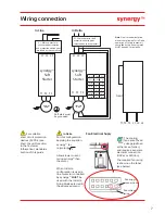
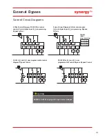
D1CO
M
D1-1I
D1-2I
D2CO
M
D2-1I
Not
Used
PT
C+
PT
C-
110-230
Vac
Earth
11
12
24
33
34
44
A0
ACO
M
0Vdc
24Vdc
AI
N
L
Description
Default
Programmable
Required rating
group 1 relay
common
relay N/
C
fault
yes
230V
ac 1A AC15,
30V
dc 0.5A Resistive
relay N/
O
fault
yes
230V
ac 1A AC15,
30V
dc 0.5A Resistive
group
2
relay
common
relay N/
O
running
yes
230V
ac 1A AC15,
30V
dc 0.5A Resistive
relay N/
O
end of
start
yes
230V
ac 1A AC15,
30V
dc 0.5A Resistive
ana
log
output
0-10
V
yes
0 to 10
V 10
mA /
4-20
mA
ana
log 0V
0V
ana
log input
0-10
V
Y
es
0 to 10
V 10
mA /
4-20
mA
control
supply
SEE T
ABLE 1 , U
S
#3
control
supply
SEE T
ABLE 1, U
S
#3
Required rating
Programmable
Default
Description
#1
Group 1 input
common
#1
SEE T
ABLE 1, U
C
yes
start/
stop
opto-coupled
input
#1
SEE T
ABLE 1, U
C
yes
None
opto-coupled
input
group 2 input
common
SEE T
ABLE 1 ,U
C
yes
reset
opto-coupled
input
not used
3 x PTC in series
(130°C)
OFF
thermistor
3 x PTC in series
(130°C)
OFF
thermistor
sig
nal ground
#3
SEE T
ABLE 1 U
S
control
supply
#3
SEE T
ABLE 1 U
S
control
supply
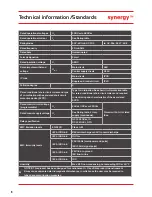
*24V
dc Specification
24V
dc 60W
Residual ripple 100mV
Spikes/switching Peaks 240mV
Turn On/Off response
No overshoot of V out
Overvoltage voltage protection output
voltage must be clamped to <30V
dc
SGY-401 to SGY-505 Control Power Consumption 120W
Wiring connection
U
C
(+10% -15%)
Notes
110
V
ac or 230
V
ac or
24V
dc.
#4
The syst
em can have eit
her a 110
/230
V
ac
mains or
24V
dc inp
ut NOT bot
h.
Table 1:- Interface Control V
oltages, 2 Amp supply (continuous).
Representative of terminal label. See T
ABLE 1, U
S
for AC
supply rating as marked on actual Synergy model.
Va
c
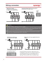
#1
The programmed digital input setting on D
1
COM,
D1-1I
,
D1-2I
must
correspond to the voltage applied to these terminals to avoid risk of damage to the equipment.
#2
The programmed digital input setting on D
2COM, D2-1I
must
correspond to the voltage applied to these terminals to avoid risk of damage to the equipment.
#3
The control supply can be 110 to 230V
ac applied to the N, L terminals
or
24V
dc applied to the 0V
dc, 24V input terminals. The correct voltage as specified must only be applied to
one
of these
supply inputs to avoid risk of damage to the equipment.
#4
Refer to Synergy Programming Manual MAN-SGY-001 for factory default settings.
Notes
Model No (s):
SGY-40
1-4-
01 to SGY-50
5-4-
0
1
U
S
(+10% -15%
)
110
V
ac or 230
V
ac or 24V
dc
Summary of Contents for Synergy SGY-401
Page 1: ...synergy Quick Start Guide SGY 401 to SGY 505...
Page 18: ...18 Notes...
Page 19: ...19 Notes...


