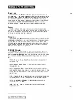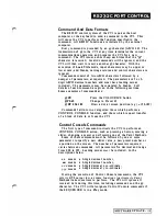
R S 2 3 2 C PO RT CO NTRO L
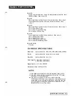
S u m mary
of how the
CV I
uses
RS232C
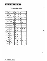
A l l bytes s e n t t o o r from t h e CVI are in terpre ted ASCII
characters. All comma nds and nu mbers (decimal and
hexadecimal) are sent as ASCII characters. For example, when
you need to send the decimal number
241
to the CVI, i t must be
sent as three consecu tive ASCII characters: "2",
"4"
and
" I ".
Similarly, the hexadecimal number
3D
must be sent as the two
ASCII characters "3" and
"0".
The CVI will communicate over a range of
Baud rates
from 300
to 9600 baud. The 1 9200 baud setting is ava ilable but cannot be
guaranteed to provide error-free operation under all circumstances
with all compu ters.
The CVI transmits, and expects to receive, bytes with seven bi ts
(Revision
5B
Software) or eight bits (Revision
6
Software) plus
parity. Where eight data bi ts are used the most significa n t bit
must always be zero in data sent to the CVI.
The CVI can be set to transmit and receive one or two
Stopbits
and any type of
Parity.
It does not check for parity errors in
received data.
The CVI uses the
RTS
and
CTS
li nes for handshaking.
When the
CTS
input is held
low
by the external computer, the
CVI will stop transmitting data until the line is taken
high
again.
The
CTS
line must be held
high
for the CVI to transmit data.
When the CVI is 'busy' it will hold its RTS output low. Any
data sent to the CVI while it is in this state will be ignored. The
CVI is 'busy' while executing any
Paint
or
Con trol Console
command initia ted via the RS232C Port.
The
DSR
input to the CVI should be held high at all times
(never switched). If DSR is not held high the CVI will not
transmit da tao
The DTR output of the CVI is always high while the power is
on.
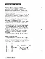
Making a connecting cable
It will be necessary to obtain or construct a cable to connect
your computer or keyboard to the CVI. The details of the pin
connections a t the computer end of the cable will depend on your
computer. Consult your computer manual or computer supplier.
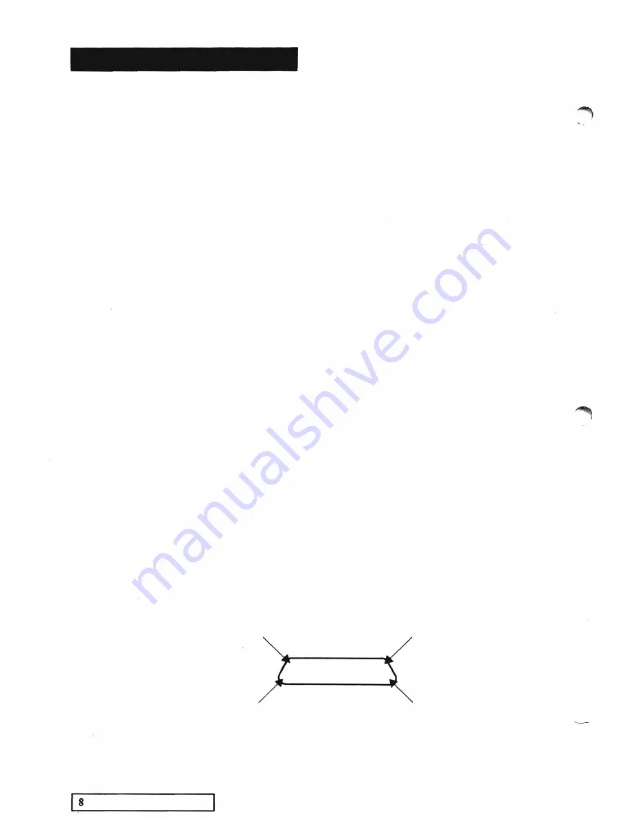
The CVI pin configuration is standard for RS232C Data Termina l
Equipment (OTE), w i t h t h e addition Power Supply pins.
Pin
2
TXD
Pin
3
RXD
Pin
4
RTS
Rear view of C.Y.I.
Pin
5
CTS
Pin 14
Pin
6
DSR
Pin
7
GND (Ground)
• • • • • • • • • • • •
Pin
1 1
- 1 2V
• • • • • • • • • • • • •
Pin
1 5
- 1 2 V
P i n
1 8
+12V
RS232C Port
Pin 1
Pin
20
DTR
Pin
25
+5V
-
SOFTWARE UPDATE
Pin 25
Pin 1 3
�
Summary of Contents for CVI
Page 1: ...r e User Manual Computer Video Instrument...
Page 4: ...Startea 2 Video Melius...
Page 102: ...33 Quad mirror Slow scan across L J _J...
Page 103: ......
Page 104: ...56 Under over stencil 57 Under over catch up 58 Push to freeze...
Page 105: ...60 L J _JI L...
Page 106: ...80 Under over texture wipe L J _J...
Page 107: ...L J _Jd r...
Page 197: ...RS232C Port ControI 1 Rev 7 Software Update 1...
Page 268: ...Glossary 1 Index 5...
Page 282: ......

