background image

2-2

I

NTRODUCTION

Chapter 2 - Installation

INTRODUCTION

The DREAM Station Channel Meter Panel is designed to be mounted directly to 
the rear of the DREAM Sidecar. One simple cable connection between the Sidecar 
and Meter Panel using the five pin XLR cable supplied, is also required.

MECHANICAL INSTALLATION

Tools Required:

• 1 x #2 Pozi-drive screw driver

• Small open-ended or adjustable spanner

Step 1

Carefully unpack the Station Channel Meter Panel.

Step 2

Remove the two screws on the rear of the Sidecar as indicated 
below. Retain these screws.

Step 3

Align the Station Channel Meter mounting brackets with the 
mounting holes on the rear of the Sidecar.

Step 4

Fasten the mounting brackets by inserting the M4 hex head bolts 
supplied with the Channel Meter. Carefully tighten the bolts with 
a spanner

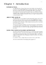
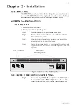
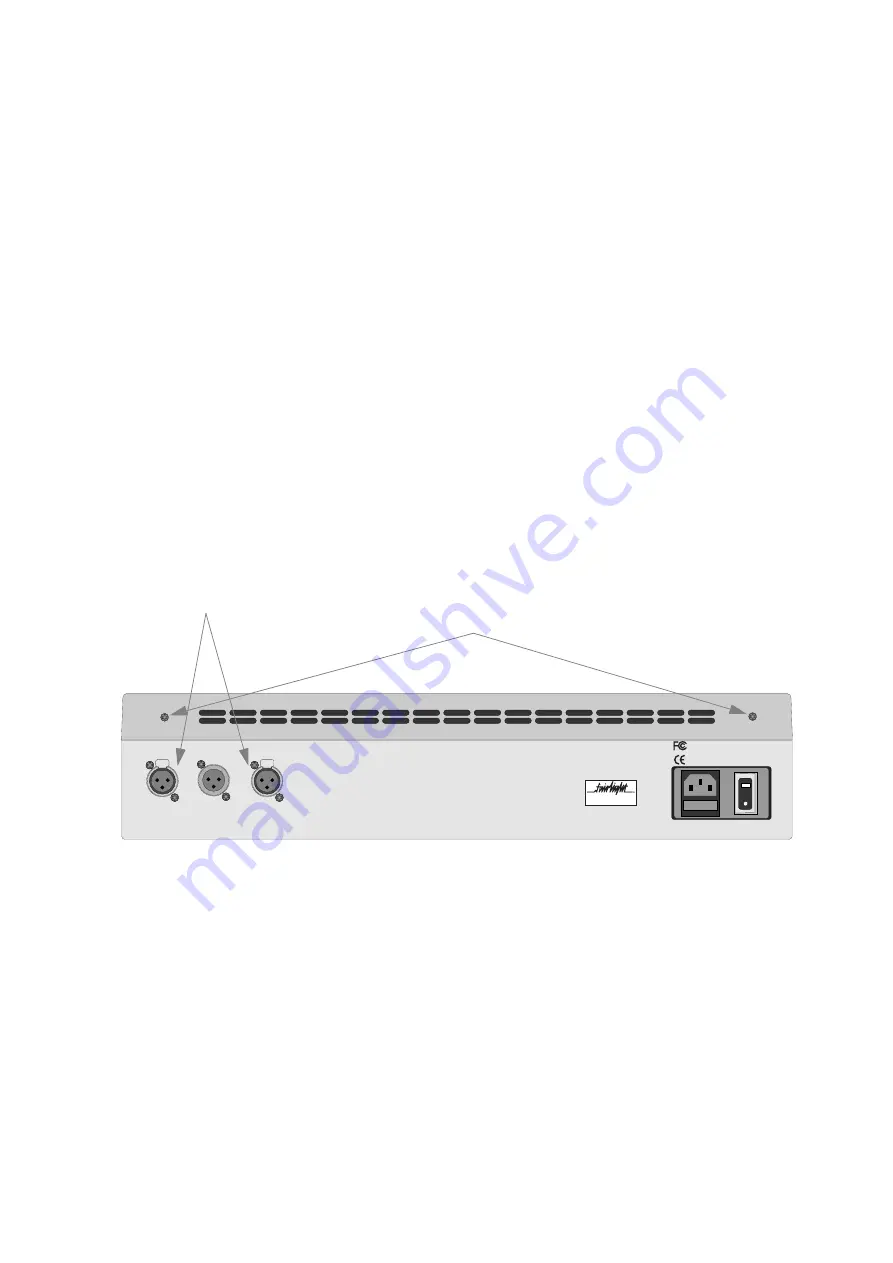
Figure 1: Station Console Rear Panel Connections

CONNECTING THE STATION METER PANEL

Step 1

Connect the 5-pin XLR USB cable (part no. AMIX119-A) from 
the female XLR labelled 

Meter

 or 

Expansion

 on the rear of the 

Sidecar to the male XLR on the Station Channel Meter Panel.

PUSH

PUSH

BE101126

Made in Australia

Expansion 1

Expansion 1

Station

PART15 CLASS A

Power Rating: AC 100 - 240V

Fuse Rating: F3.15A 250V

50 - 60 Hz  2A

replace only with the same type and rating of fuse.

CAUTION: For continued protection against the risk of fire,

CAUTION: Disconnect power before changing fuse.

Manufactured in Sydney, Australia

by Fairlight ESP Pty. Ltd.

Fairlight personnel.

Model Number: 1BE1002

Warning: No user serviceable parts

inside. Refer service to authorised

Meter Panel 

Mounting Screws

Meter Connectors 

Summary of Contents for DREAM Station SCP1

Page 1: ...Station Channel Meter Panel Installation Manual Document No 220 Part No DBE1201 A DREAM Software Version 1 1 SCP1...

Page 2: ...r implied with respect to the system s performance or fitness for a particular purpose In no event will Fairlight ESP Pty Ltd be liable for direct or indirect damages arising from any defect in the pr...

Page 3: ...t 45th Street Penthouse New York NY 10036 USA Tel 1 212 819 1289 Fax 1 212 819 0376 United Kingdom France Fairlight ESP Limited Unit 12 Spectrum House 32 34 Gordon House Road London NW5 1LP England Te...

Page 4: ...UCTION 2 2 MECHANICAL INSTALLATION 2 2 Tools Required 2 2 CONNECTING THE STATION METER PANEL 2 2 Connecting Two Meters 2 3 CONFIGURATION 2 3 USB Installation 2 3 Cons con 2 3 Configuring Two Meter Uni...

Page 5: ...used in conjunction with the DREAM Station and Sidecar Installation and User Manuals to obtain complete instruction in the use and instal lation of the complete system This manual is designed to fami...

Page 6: ...2 1 NOTES...

Page 7: ...nserting the M4 hex head bolts supplied with the Channel Meter Carefully tighten the bolts with a spanner Figure 1 Station Console Rear Panel Connections CONNECTING THE STATION METER PANEL Step 1 Conn...

Page 8: ...lation The USB driver for the Meter Panel must be installed the first time it is connected to the system Step 1 Ensure the Meter Panel is connect to the Station and that the Sta tion is running Step 2...

Page 9: ...re 3 ConsCon Window Configuring Two Meter Units If two Channel Meters are to be fitted the Fairlight distributor must be informed prior to shipping in order for the panel configuration of the second m...

Page 10: ...3 1 NOTES...

Page 11: ...USB and DC Power connection Connector 5 Pin XLR Male DIMENSIONS AND WEIGHT DREAM Station Main Meter Panel Note All specifications subject to change without notice XLR5 SIGNAL PAIR PIN 1 USB 1 PIN 2 0...

Page 12: ...D Depth 3 2 Dimensions 3 2 DREAM Start 2 3 F Found New Hardware 2 3 H Height 3 2 M Mechanical Installation 2 2 Meter 2 2 Modify Panel 2 4 R Remove Panel 2 4 S Specifications 3 2 Station 2 2 U USB 2 2...

Reviews: