


2-4
T
ESTING
AND
C
OMMISSIONING
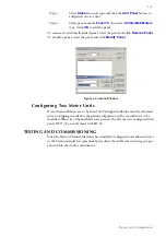
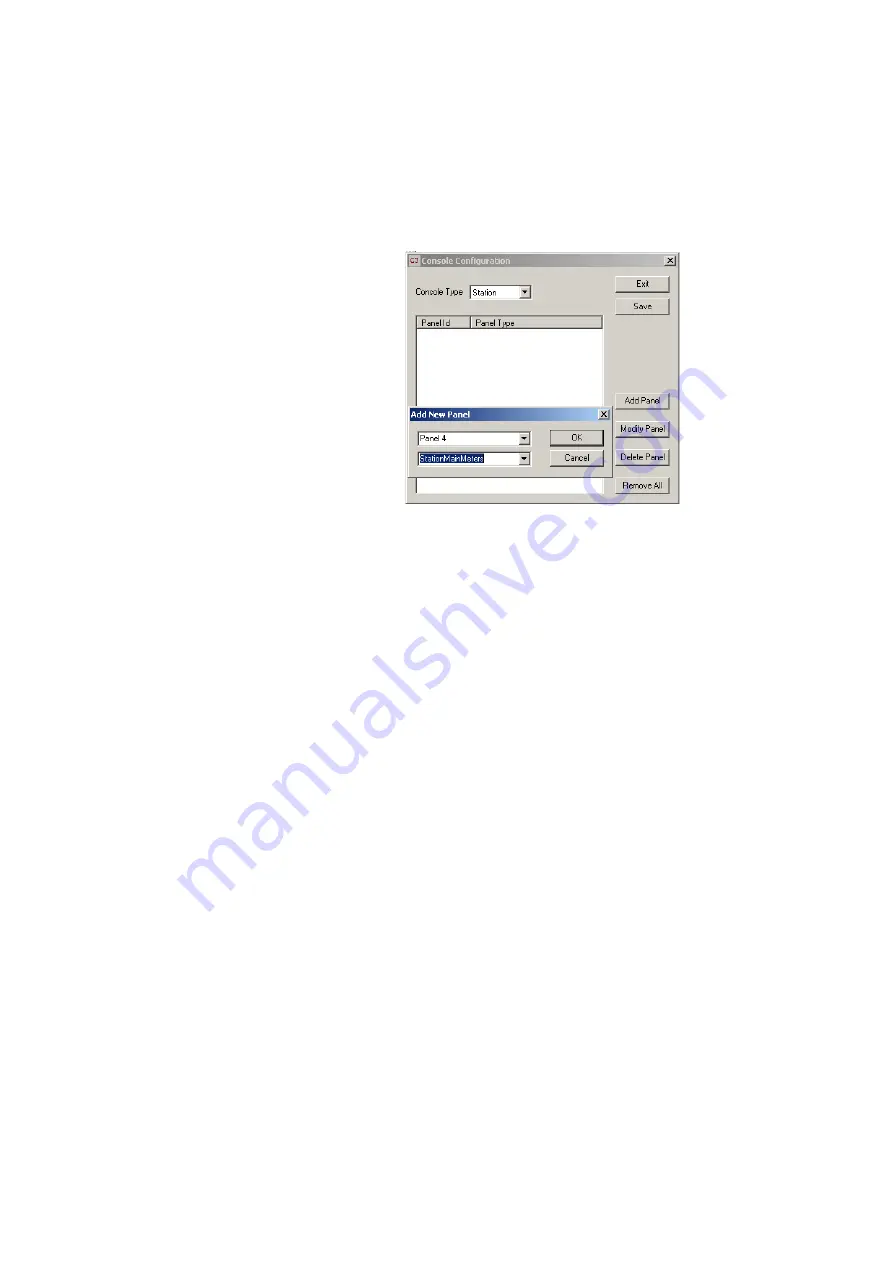
Step 3
Select
Station
console type and click the
Add Panel
button to
add panels one at a time.
Step 4
Select panel number
Panel 15
, then select
StationMainMeters
type. Click
OK
to add the panel.
To remove an accidentally added panel, select the panel and click
Remove Panel
.
To modify a panel, select the panel and click
Modify Panel
.
Figure 3: ConsCon Window
Configuring Two Meter Units
If two Channel Meters are to be fitted, the Fairlight distributor must be informed
prior to shipping in order for the panel configuration of the second meter to be
modified. When two Channel Meters are present, the first meter is configured with
panel ID 15, the second meter with ID 16.
TESTING AND COMMISSIONING
Once the Station Channel Meter has been installed, configured and calibrated, refer
to the Station manual for operational procedures that will assist in testing its oper-
ation within the studio environment.
Summary of Contents for DREAM Station SCP1
Page 6: ...2 1 NOTES...
Page 10: ...3 1 NOTES...


