background image

Service Manual 

C

HAPTER 

6


-


T

HE 

SX-48


C

ONFIGURATOR


July 24, 2008 


SX-48 Page 

28 

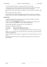
You can set up the Sync source and Sample Rate, and also Pull Ratio setting. This can also display 

the reason for a lock failure such as "Sync Source not connected".  

With AES or W-C sync input it will show the actual input sample rate and pull ratio if not locked. 


Diagnostics Section 


Read I/O cards 

This gives you the I/O card configuration in a particular unit. 


Read Patching


This currently gives you a readout of the current patching scheme. 


Summary of Contents for SX-48

Page 1: ...SX 48 Service Manual 24 July 2008 Version 1 0...

Page 2: ...ct in the product or its documentation Further FairlightAU Pty Ltd will not accept any liability for any programs sounds audio recording or sequences stored in or used with Fairlight products includin...

Page 3: ...Environment 11 Cabling 12 User Interface 12 Factory Reset 12 Setup 13 CHAPTER 3 PINOUTS 15 Analog Inputs 15 Analog Outputs 16 AES Inputs and Outputs 17 RUNNING SX 48 IN A DREAM II SYSTEM 18 Sync 18 A...

Page 4: ...SX 48 Page 6 Analog Inputs and Outputs 31 AES EBU Inputs 31 AES EBU Outputs 31 Synchronization 31 Dimensions Weight and Power Requirements 32...

Page 5: ...g off the power and making sure that the unit is properly grounded Fitting and Changing Boards Static Precautions SX 48 installation may involve fitting of electronic circuit boards Care must be taken...

Page 6: ...Board All boards are fitted using connectors that press together Excessive force is not required I O boards use white Teflon guides to locate easily Ensure that the Teflon posts are correctly lined up...

Page 7: ...28 channels at up to 96 kHz Note that only the first 48 channels can actually be used at 48 kHz because the unit only supports that number of analog or AES digital channels Sync 1 The Sync 1 board pr...

Page 8: ...itting boards see the section Fitting and Changing Boards In particular note the section on orientation of boards because incorrect orientation can cause severe damage to the unit Order of Boards Any...

Page 9: ...be given at the rear of the unit as it is quite heavy People installing the SX 48 should exercise caution in lifting it into place as back injury can result from incorrect lifting technique The SX 48...

Page 10: ...ne to use The following connectors are used Video Sync BNC Word Clock BNC AES sync XLR TSCP BNC All connectors are labeled Pinouts for these connectors can be found in Chapter 4 Pinouts page 15 User I...

Page 11: ...put at that position If an input or output LED is orange it means there is a digital input or output at that position If an input or output LED is off it means there is no correctly functioning input...

Page 12: ...Service Manual CHAPTER 3 INSTALLATION PROCEDURE July 24 2008 SX 48 Page 14 The unit now exits Setup Mode and is ready for use...

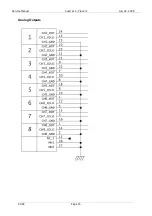
Page 13: ...Service Manual CHAPTER 4 PINOUTS July 24 2008 SX 48 Page 15 Chapter 4 Pinouts Analog Inputs...

Page 14: ...Service Manual CHAPTER 4 PINOUTS July 24 2008 SX 48 Page 16 Analog Outputs...

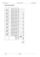
Page 15: ...Service Manual CHAPTER 4 PINOUTS July 24 2008 SX 48 Page 17 AES Inputs and Outputs...

Page 16: ...house sync is being used it should be connected to both boxes and both boxes should have video selected as the sync source Audio Connection SX 48 is used with DREAM II as follows Analog Input MADI DRE...

Page 17: ...3 This line tells the system how many MADI channels it should display By default there are zero inputs and zero outputs before you connected the SX 48 or any other MADI device so it reads IO_CONFIG 3...

Page 18: ...II SYSTEM July 24 2008 SX 48 Page 20 To do this connect the SX 48 to your Ethernet hub using a standard networking cable Your DREAM II system will automatically find the SX 48 and send commands to it...

Page 19: ...e Start All Programs Fairlight FMC FMC Utils SX48 Configurator Please read this section completely before you attempt to use the SX 48 configurator All files used by the SX 48 Configurator are install...

Page 20: ...unit by choosing a particular unit from the drop down window Setting the Room number and Unit number then simply click on the Set New Room ID button The Room ID accepts any single alphanumeric charac...

Page 21: ...ently on the wrong subnet For example a new unit or a defaulted unit set to 192 168 3 253 can be plugged in to a new network and the IP changed to match without any other intervention It is even now p...

Page 22: ...Click on the Firmware Version button to read the current firmware versions for any particular SX 48 unit chosen in the drop down window You will see the following information displayed in the info wi...

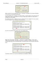
Page 23: ...upper right You will see a progress bar indicating that the download is taking place You will also see information scrolling in the info box of the Network Download Utility on the progress of the upgr...

Page 24: ...essfully upgraded with the new firmware Searching for boards on port 2000 Search Ping response from 192 168 3 223 port 2000 SX48 223 1 2 068 Room 1 Unit 3 Search Ping response from 192 168 3 234 port...

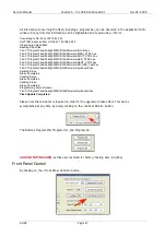
Page 25: ...s Fairlight FMC Utils Firmware AES_CTRL hex File C Program Files Fairlight FMC Utils Firmware AES2_CTRL hex File C Program Files Fairlight FMC Utils Firmware AO_AES_Test hex File C Program Files Fairl...

Page 26: ...an also display the reason for a lock failure such as Sync Source not connected With AES or W C sync input it will show the actual input sample rate and pull ratio if not locked Diagnostics Section Re...

Page 27: ...utton may be used at any time to return the SX 48 s patching scheme to its default state Note If you patch the OSC to all 48 MADI streams then the Output LEDs will light up not the Input LEDs This is...

Page 28: ...ion of digital input signals if their sample frequency is not locked to that of the SX 48 system To use this facility the I O config txt file must be edited to include some new information Note this f...

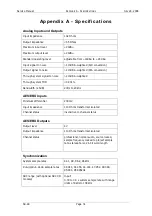
Page 29: ...h system THD 0 001 Bandwidth 25dB 20Hz to 20kHz AES EBU Inputs Minimum differential 200mV Input impedance 110 Ohms transformer isolated Channel status insensitive to channel status AES EBU Outputs Out...

Page 30: ...sions Weight and Power Requirements CAUTION Double pole neutral fusing Disconnect power before changing fuse or servicing Width 484 mm standard 19 inch rack mount Depth 428 mm Height 89 mm 2 standard...

Reviews: