Assembly Instructions
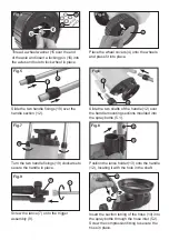
Fig.1
Fig.2
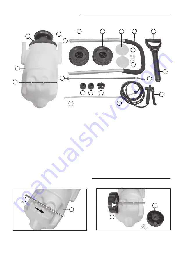
Slide the wheel axle (14) through both of
the axle mounting brackets located on the
bottom of the tank (5).
Slide one of wheels (3) onto the axle.
14
5
3
3
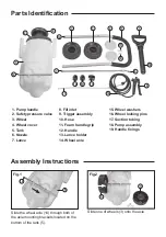
1. Pump handle
2. Safety pressure valve
3. Wheel
4. Wheel cover
5. Tank
6. Nozzle
7. Lance
Parts Identification
8. Fill inlet
9. Trigger assembly
10. Hose
11. Foam handle grip
12. Handle
13. Lance holder
14. Wheel axle
15. Wheel washers
16. Wheel locking pins
17. Suction tubing
18. Pump assembly
19. Handle fixings
1
7
17
14
3
3
9
4
11
19
19
13
18
16
15
10
12
5
6
2
8


