
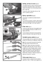
Safety pressure valve
(Fig.15)
The safety pressure valve (2) will open when
the pressure exceeds 2.5bar. It can also be
opened manually to vent remaining pressure
prior to opening.
To open the valve manually, pull up on the
valve to release pressure.
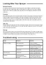
Spray operation
(Fig.16)
The sprayer is operated by depressing the
trigger (9).
For continuous spraying, pull the metal locking
catch (9.1) forward and locate onto the plastic
lug, locking the trigger in the open position.
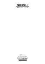
Flow rate
(Fig.17)
The force of the spray can be regulated using
the flow adjustment dial (9.2) located on the
trigger assembly.
Turn the dial anti-clockise for increased flow
rate and clockwise to decrease the flow rate.
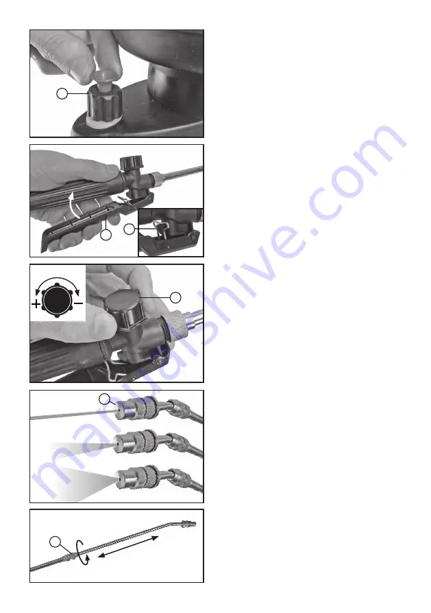
Variable spray pattern
(Fig.18)
The spray pattern can be varied from a fine jet
through to a wide fan by rotating the nozzle (6).
Note:
Do not undo the nozzle too far as this
will cause liquid to leak from the rear.
Note:
If the nozzle continues to drip after
the trigger handle has been shut off, there is
probably air in the discharge system (nozzle,
handle, tap and hose). Purge the system by
turning the nozzle to jet and operating the
trigger on and off in short bursts, until the
liquid shuts off cleanly. Collect any liquid in a
separate container to use later.
Telescopic lance
(Fig.19)
Unscrew nut (5.1), pull lance out to desired
length from 520 to 1150mm and retighten nut.
2
Fig.15
6
9
9.1
9.2
Fig.18
Fig.16
Fig.17
Fig.19
7.1


