7.
SEWING MACHINE SETTING OPERATIONS
7.2 Shuttle position setting.
To set the shuttle position, proceed as follows:
- Turn off the machine using the main switch and disconnect the machine cable from the electricity
supply.
- Open the front door of the sewing head.
- Check the shuttle position as follows:
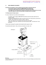
- Turn the hand wheel until the reference notch of 42 is lined up as can be seen on the cam
n. 6406.00.
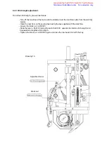
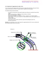
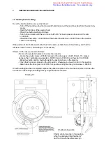
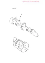
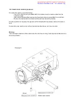
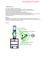
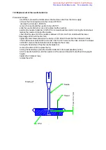
- Check that the shuttle n. 6309.00 and the shuttle thrust device n. 6303.00 are in the position
shown in the drawing.
If the position of the shuttle and shuttle thrust is the same as that shown in the drawing, and that the
reference notch is on 42, then setting is not necessary.
If this is not the case, proceed as follows:
- Remove the protection plate on the mechanical parts
- Loosen the groub screws n. 90606.5 placed on the drive gear n. 6220.00 (tab. 17), placed
between the 2 self-aligning supports (n. 6307.00 and n. 6308.00), on the shaft n. 6306.00,
- Bring the shuttle and the shuttle thrust to the position shown in the drawing.
- Check that the cam is placed on the 42 position; otherwise you have to put it in this position,
- Return back the drive gear n. 6220.00 in its position and tighten the groub screws n. 90606.5.
Once the setting has been completed, replace the protection plate on the mechanical parts, and close the
front door on the sewing head using the key supplied with the machine.
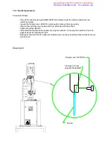
Drawing 19
Shuttle start position
Shuttle control must be in this position
when the graduated disk has the 42°
notch in line with the reference sign
Generated by Foxit PDF Creator © Foxit Software
http://www.foxitsoftware.com For evaluation only.

