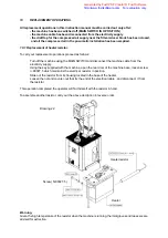
background image

9. MACHINE USE.

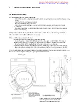
9.1.  Description of the function —Action —> Consequence Cycle.

The functioning sequence of the Mod. 525 proceeds as follows:

1) Turn on the MAIN SWITCH on the electrical control panel, turning it to position N° 1—> the main motor
    will start running at minimum speed, but without turning the shuttle.

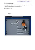
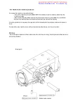
2) Turn the two switches N° 4. and N° 6  towards the right: the temperature is now set at the maximum
    possible. After about 10 - 15 minutes, when the spool holder support id hot enough, to the point where
    you cannot place your hand on it, turn the knob in an anti-clockwise direction, to reduce


 the

    temperature and bring it to the desired temperature.
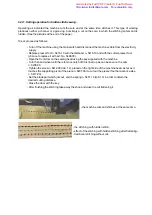
    Warning:

To obtain the best working temperature, test by pulling the thread downwards from the spool holder. The
    thread should run smoothly , without resistance, or having to be pulled sharply. If this is not the case.
    this means that the temperature is too low, or that the spool is not wound correctly and evenly.

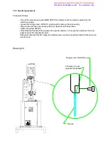
3) The presser foot is raised: place the shoe on the horn, and with your left hand, take a piece of thread from
the spool long enough to be able to hold the thread against the sole with your thumb, to the left of the
needle.

4) Press the control pedal lightly:
    —> the presser foot will be lowered automatically, blocking the shoe in place for stitching.

5) Press the pedal further:
    —> the gear will mesh electronically —> the motor will increase rotation speed until it reaches the
    desired sewing speed.

    Warning:

    Let the machine guide the shoe during stitching: the shoe must not be pushed or pulled, so the operator
must only guide and follow the machine movement, taking care to follow the sewing line desired.
    The horn will rotate on itself during stitching, and will assume the correct position for easy sewing as the
operation continues.
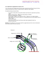
    A headless setting screw (hexagon head bolts) located under the control pedal means that the sewing
speed can be set at the speed the operator finds most convenient, and even if the pedal is pressed further,
the

speed will not increase.

    This method is very useful, above all when beginning to learn on the machine. Later the pedal block can
be adjusted at higher speed rate up to the maximum possible on the machine.

    - Sewing speed depends on the control pedal: the further it is pressed down, the more the sewing speed
increases.

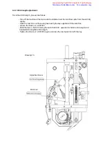
    - The brake and gears  which work during the start-up and stopping of sewing operations, are positioned
on an axis with the main motor and form a single block with the motor.

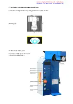
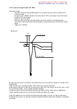
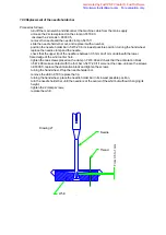
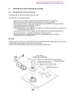
8.3  Position of article to be stitched.

The article to be stitched must be placed between the horn tip and the presser foot.

Generated by Foxit PDF Creator © Foxit Software

http://www.foxitsoftware.com   For evaluation only.

Summary of Contents for F525 N

Page 1: ...SERIAL N YEAR OF CONSTRUCTION Manual Revision Number 3 Builder Company and authorized to supply the Technical Documentation FALAN s r l Via Buscaglia 14 27029 VIGEVANO ITALIA Tel 39 0381 346373 Fax 39...

Page 2: ...SERIAL N YEAR OF CONSTRUCTION Manual Revision Number 3 Builder Company and authorized to supply the Technical Documentation FALAN s r l Via Buscaglia 14 27029 VIGEVANO ITALIA Tel 39 0381 346373 Fax 39...

Page 3: ...ve suffered during transport 6 2 2 Machine cleaning procedure 6 3 Connection to external energy supply 6 3 1 Connection to electrical energy supply 6 3 2 Connection to compressed air supply 6 4 Contro...

Page 4: ...lacement 10 10 Flexible sheating for the horn replacement 11 ACCESSORIES 11 1 Heating equipment 11 1 1 Spool stripper plug adjustment 11 2 Shuttle spool preparation using the spool winder 12 MOUNTING...

Page 5: ...ribed in this instruction manual must be carried out ONLYAFTER having turned off the machine MAIN SWITCH IN O POSITION disconnected the machine cable from the main electrical supply closed the compres...

Page 6: ...Opanka of shoe soles The sewing operation is carried out by a needle and shuttle system mechanically run by a transmission shaft cam and gears controlled by an electronic motor and V belt The machine...

Page 7: ...alled by the manufacturer to save the operator from injury during work operations These protections must not be removed while the machine is running 2 IT IS EXTREMELY IMPORTANT that the operator pays...

Page 8: ...par 15 9 Electrical installation transformer safety instructions into the par 16 10 Some operations described in this instruction manual must be carried out with the motor switched off and the electr...

Page 9: ...on the machine OBLIGATORY TO READ THE INSTRUCTIONS MANUAL BEFORE USING THE MACHINE CAUTION DON T REMOVE THE SAFETY DEVICES CAUTION SURFACEAT THERMIC RISK CAUTION RISK OF PERFORATION OBLIGATORY THE US...

Page 10: ...2 rivets of 3 mm Fastened by a mechanical connection with 4 rivets of 3 mm Fastened by a mechanical connection with 2 rivets of 3 mm Fastened by a mechanical connection with 4 rivets of 3 mm front vie...

Page 11: ...to 15 mm Maximum thickness sewn 30 mm TECHNICALDESCRIPTIONOF MAINMOTOR STITCHING CONTROL Monophase electronic motor Power 1 Hp 0 75 kW N B For technical details of the elctrical motors on the machine...

Page 12: ...mer Under no condition must the cam and kinetic positions be changed in order to modify the machine s running sequence There a chance to change the speed through the sewing machine motor parameters Th...

Page 13: ...the head of the machine see drawing 2 the hook with the lifting cables Raising and handling of the machine should be carried out by a small crane driven by an expert One of the handling crew must be o...

Page 14: ...hat the hook into the eyebolts is strictly fixed using the special bolts to prevent dangerous falls Before raising the machine with the crane make sure that the 4 brackets are tightly screwed to the p...

Page 15: ...t and to protect the various machine parts by spraying with anti rust paint During transport the horn must be mounted on the machine Never move the machine by pushing it on a trolley If there is no ot...

Page 16: ...Mod 525N machine are shown in the drawing below Drawing N 5 During machine installation the pallet fixing brackets are removed so the width of the machine is reduced from 689 mm to 550 mm Generated by...

Page 17: ...2 Mod 525N Base For correct functioning the machine does not need to be bolted to the flooring Drawing N 6 Generated by Foxit PDF Creator Foxit Software http www foxitsoftware com For evaluation only...

Page 18: ...in engine light spot front head shuttle needle foot control panel Horn spool winder block technical information plate Pedal electricalequipment shuttle horn solenoid spool shuttle plaque accident prev...

Page 19: ...hine For correct use of the machine and to permit safe and easy repairs and maintenance it is adviseable to respect the minimum distances shown in the drawing Drawing 8 Generated by Foxit PDF Creator...

Page 20: ...nd pneumatic components electric motors transmission V belt horn all jutting out parts of the machine 6 2 2 Machine cleaning procedure Clean the machine carefully removing all dust dirt and foreign ma...

Page 21: ...components on the machine are the same as those on the main supply line at the user s factory The voltage and the frequency of the machine are shown on a metal plate attatched to the machine column Dr...

Page 22: ...e air supply to the machine even when the machine is connected to the compressed air line see paragraph 6 4 2 air pressure adjustment The filter reducer block is located on the back wall of the machin...

Page 23: ...6 4 1 Correct motor rotation direction check The Machine has an engine 220V 50 60 Hz Monophase and does not require verification of the rotation Drawing 11 Generated by Foxit PDF Creator Foxit Softwa...

Page 24: ...knob located on the filter reducer block The established pressure rating is visible on the pressure gauge dial Warning Recommended pressure 5 bar Drawing 12 Pressure reducer Pressure gauge Condensati...

Page 25: ...ead using the key supplied with the machine Loosen the block nut n 90808 5 Slide the lever n 5441 00 along the sector 6408 00 upwards to shorten stitch length and downwards to lengthen stitch length T...

Page 26: ...anner In a clockwise direction tightening the screw the pinion is lowered In an anticlockwise direction loosening the screw the pinion is raised Insert the pinion again Insert the tip fixing it in pos...

Page 27: ...bar loosen it to lower the bar Tighten the block nut and close the door with the key Drawing 15 Block nut N 90809 5 Grub screw N 90520 5 6 4 6 Setting of the presser foot bar advance step art n 5417 2...

Page 28: ...the front door on the sewing head using the key supplied with the machine Unscrew the screw n 90080 5 with the spanner Turn the hexagonal nut n 5450 10 in an anti clockwise direction to increase the...

Page 29: ...washer n 2322 Turn the knurled washer n 2321 for setting the thread tension spring load n 2320 Block the washer n 2321 by tightening the counter washer n 2322 Once the setting has been completed close...

Page 30: ...ey supplied with the machine Turn the hand wheel until the reference notch of 00 is lined up as can be seen on the cam n 6406 00 Tighten the screw n 6412 00 tab 12 placed on the right side of the mach...

Page 31: ...resses part n 5443 00 upwards so that the plug n 5469 00 makes contact Warning If the part 5443 00 is not functioning correctly this has an influence on the pressure foot bar Part N 5443 00 Spring N 5...

Page 32: ...llows Remove the protection plate on the mechanical parts Loosen the groub screws n 90606 5 placed on the drive gear n 6220 00 tab 17 placed between the 2 self aligning supports n 6307 00 and n 6308 0...

Page 33: ...the machine base If the lever n 6214 00 thread passage hole reference is in its highest position the setting is not necessary If not proceed as follows Open the back door on the machine base Loosen t...

Page 34: ...ontrol panel door is placed on the left side of the column 8 SETTING UP THE MACHINE READY FOR WORK The machine is designed with the operating position in front of the machine Drawing 20 Generated by F...

Page 35: ...thread end and pull it through enough so that you find the thread already soaked in the oil emulsion in your hand Keeping the thread taught tie it to the spring n 0539 on the side of the horn Warning...

Page 36: ...holder in its housing remembering that the indentation on the side of the spool holder must face downwards Warning Machine threading must always be carried out with the machine stopped and the MAIN SW...

Page 37: ...Drawing 21 Generated by Foxit PDF Creator Foxit Software http www foxitsoftware com For evaluation only...

Page 38: ...utomatically blocking the shoe in place for stitching 5 Press the pedal further the gear will mesh electronically the motor will increase rotation speed until it reaches the desired sewing speed Warni...

Page 39: ...orn where the curved horn is being used for Blake stitching 7 To start a new stitching operation repeat the sequence described above Testing has shown that the noise level for the operator is not over...

Page 40: ...icity supply Using the key supplied with the machine open the rear door of the machine base loosen screw n 90027 5 which maintains the electrical resistor in position Slide out the resistor from its h...

Page 41: ...iconnect the wire from the terminal faston Once the operation is completed the operator will find himself with the resistance and electrical wire in hand To assemble a new resistor carry out the proce...

Page 42: ...5 Check that the flat side of the needle is facing the operator in this way the needle will be at an angle of about 45 towards the right Take great care that this 45 angle is maintained even on those...

Page 43: ...needle is used 5 5 6 7 so that the thread can pass easily through the sole thickness However with a leather sole a medium sized needle is better 4 4 5 5 to avoid making too large a hole in the leather...

Page 44: ...er of the needle shank If this is not the case using the tweezers shift it to the left or right as necessary When using the tweezers make sure you grip the rear part of the loop opener and not the poi...

Page 45: ...placement 2 For the vertical setting of the loop opener support lever position the needle clamp bar n 5415 20 in its lowest possible position Control that the distance between the tip of the loop open...

Page 46: ...ip fixing it in position with the two grub screws starting with the first one from the top of the horn Warning if the housing of the tip of the horn where the whirl is has worn out too much the whirl...

Page 47: ...needle is between 0 5 mm and 1mm underneath the lower flared edge of the whirl center hole tighten the two screws placed on the clamp n 7418 00 and check that the antirotation block n 5474 00 makes co...

Page 48: ...o block the article driven transmission clutch and therefore the flexible cord the assembling done check that the article and the article have a minimum play about 1 mm remove the tip and reassemble i...

Page 49: ...is obtained using the three way switch HEATER RESISTOR SWITCH Before use the sewing thread must be soaked in the wax or parafin and then wound on the spool by the spool winder To soak and wind the thr...

Page 50: ...TCH Place the thread bobbin in the support set in the lower right hand side of the machine base access obtained by opening the front door Unwind the end of the thread from the bobbin pass the thread t...

Page 51: ...the spacer Only just tighten the 4 screws n 90072 5 and center the horn with slight movements by tapping the horn base with a resin hammer Control that the horn is correctly centered by removing the w...

Page 52: ...Drawing 30 Opanka horn with thread path Generated by Foxit PDF Creator Foxit Software http www foxitsoftware com For evaluation only...

Page 53: ...hat the male transmission n 5525 02 is well set in the correct housing art n 5516 00 Only just tighten the 3 screws n 90075 5 and center the horn with slight movements by tapping the base of the horn...

Page 54: ...control and adjustment of cogged pinion for whirl control see par 6 4 4 Each week Check control of the antirotation block play n 5474 00 see inside the par 10 8 Each month Filter inspection Compressed...

Page 55: ...oil the inside of the shuttle well before inserting the bobbin support Lubrify the thread passageof the whirl regularly putting a drop of oil after having removed the whirl cover plate Once a day put...

Page 56: ...action plates Problem Thread breakage Reasons and solutions Low quality thread employed Incorrect whirl position Horn thread too taught loosen with knob n 2321 Needle placed too high or too low Needle...

Page 57: ...only when the machine is running Reasons and solutions The pinion and whirl have damaged cogs or are not set correctly The whirl is forcing in its housing or scrapes against the horn cap The adjustin...

Page 58: ...4 1 shuttle bearing 92308 5 spare replacement parts for curved horn for Blake stitching Quantity machine part code number 10 cogged threader for whirl 0533 1 whirl cover plate 5505 00 5 cogged pinion...

Page 59: ...Roller Nut Transport point Grub screw M5x6 P P E I Presser foot Plate fixing screw Whirl Needle n 3 1 2 Guide Stud Roller Nut Transport point Grub screw M5x6 P P E I Presser foot Guide spacer Thread...

Page 60: ...inated separately Pneumatic and electrical components such as valves electrovalves pressure regulation equipment switches transformers etc must be dismantled for re use if still in good condition or i...

Page 61: ...en the operator makes the above mentioned operations that nobody put any parts of his body like hands or fingers between the foot holder bar and the horn of the machine to avoid squashings or lacerati...

Page 62: ...running The machine must always be switched off MAIN SWITCH IN O POSITION and the machine cable disconnected from the electricity supply 18 Before starting up the machine lubrify all moving parts 19 S...

Reviews: