33
Mounting the hydraulic pump
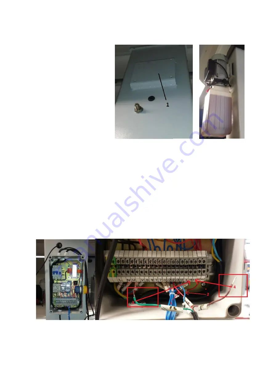
1.
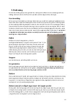
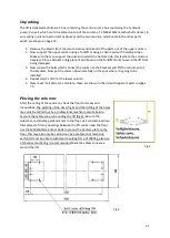
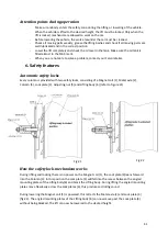
Place the pump against the
square plate (1, fig.7) on
column A.
2.
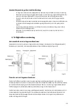
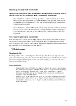
Mount the pump to the plate
using the M8x20mm bolts,
washers and nuts (fig.8).
Connecting the electrical components
CAUTION! Only a professional electrician is allowed to connect all of the electrical wiring, damage
due to faulty connecting is not covered by warranty.
1.
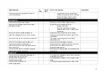
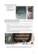
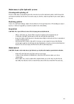
Place the control unit (fig.9) against column A and mount it with the 4 bolts that come with
the unit.
2.
Inside the column you will find a cable out of which 4 wires protrude, blue, red, green and
brown. Stick the wire outwards through the hole above the control-unit. Now loosen one of
the swivels on top of the control-unit and stick the cable through. Tighten the swivel
afterwards.
3.
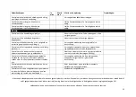
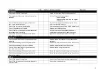
Now connect the blue wire (2, fig.10) to position 15, the red wire (1, fig.10) to position 17,
the green wire (3, fig.10) to position 19 and the brown wire (4, fig.10) to position 21. These
wires are connected to the lower limit switch.
4.
Now you can stick all cables coming out of the control-unit inside the column, through the
hole above the unit. Now place all cables upwards through the bracket (1, fig.11a), the
Fig.7
Fig.8
Fig.9
Fig.10

