FOX3-KMD H
ARDWARE
M
ANUAL
V
ERSION
1.0.1
6.1.1.2.
How to use I/O1 (pin 4)
This pin has dual functions. It is controlled by the internal firmware of FOX3-KMD. Therefore, the user must
define whether to use it as analog or digital pin. The configured digital pin can also be used as input or output
while the if configured as analog pin it can only be used as input.
The command
PFAL,IO
0
.Config
controlls its functionality.
$PFAL,IO
0
.Config=AI,2,11
//
0
= I/O1
;
AI
= analog;
2
and
11
= min. and max. voltages for Low and High events
$
PFAL,IO
0
.
Config=DI,5,10
//
1
= I/O2;
DI
= digital input;
5
and
10
= min. and max. voltages for Low and High events
If you want to use this pin as digital, then use one of the following PFAL command to trigger it to high or low:
$PFAL,IO
4
.Set=high
//
4
= I/O1;
high
= sets output to high
$PFAL,IO
4
.Set=low
//4
= I/O1;
high
= sets output to high
$PFAL,IO
4
.Set=cyclic,2000,1000
//4
= I/O1;
cyclic
= sets output to high for 2 seconds and low for 1 seconds.
The High and Low levels can be set with PFAL command (see above). When the internal firmware detects
changes on the analogue/digital input, then a
Falling
or
Rising
edge event is respectively triggered. This events
can be used to send alarms and messages to the server or via SMS.
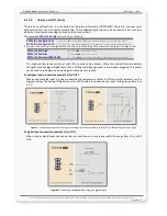
As analogue input: connection example 1 (for I/O1):
When used as analog input, e.g when connected to a temperature sensor (a NTC resistor for instance) use the
diagram below. The analog-to-digital converter (ADC) inside the device has an input voltage range from 0 to
2.5 V.
Figure 3:
Connection example 1 when using it as analog input and connected to an NTC (left) or Tachometer generator (right)
As digital input: connection example 1 (for I/O1):
When used as digital input you can set
V
IN(LOW)
and
V
I
N(HIGH)
to any levels within the range from +0 to +32.0
VDC.
Figure 4:
Connection example when using it as digital input.
This confidential document is a property of FALCOM GmbH and may not be copied or circulated without previous permission.
Page
16
of 23


