GPS-RECEIVER JP7-T
VERSION 1.02
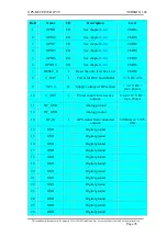
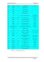
Ball
Name
I/O
Description
Level
1
GPIO1
I/O
CMOS
2
GPIO0
I/O
CMOS
3
GPIO7
I/O
CMOS
4
GPIO5
I/O
CMOS
5
GPIO6
I/O
CMOS
6
GPIO10
I/O
CMOS
7
RESET_N
I
Reset the unit, if Active Low
CMOS
8
V_BAT
I
Power for RTC and SRAM
+3 V DC ±5%
9
VC3.0
O
Supply voltage of RF section
+ 3.0 V DC /
max. 25 mA
10
V_ANT
I
Power supply for an active
antenna
Up to +12 V DC /
max. 25 mA
11
RF_GND
Analog ground
12
RF_GND
Analog ground
13
RF_IN
I
GPS signal from connected
antenna
50 Ohms @ 1.575
GHz
14
GND
Digital ground
15
GND
Digital ground
16
GND
Digital ground
17
GND
Digital ground
18
GND
Digital ground
19
GND
Digital ground
20
GND
Digital ground
21
GND
Digital ground
22
GND
Digital ground
23
GND
Digital ground
24
GND
Digital ground
25
GND
Digital ground
26
GND
Digital ground
This confidential document is the property of FALCOM GmbH and may not be copied or circulated without permission.
Page 26


