GPS-RECEIVER JP7-T
VERSION 1.02
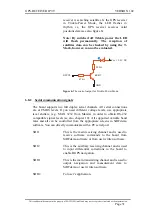
receiver is searching satellites. Is the GPS receiver
in Trickle-Power Mode, the LED flashes in
rhythm, i.e. the GPS receiver receives valid
positions data (see also figure 6).
Note: By switched off Trickle power the LED
will flash permanently. The reception of
satellites data can be checked by using the T-
Mark, however, can not be evaluated.
RFPC0
330
Ω
Vcc = 3.3 V DC
BC817
47 k
Ω
GND
figure 6:
The control output for Trickle-Power Mode.
6.8.2 Serial communication signals
The board supports two full duplex serial channels. All serial connections
are at CMOS levels. If you need different voltage levels, use appropriate
level shifters, (e.g. MAX 3232 from Maxim) in order to obtain RS-232
compatible signal levels (se also chapter 10). All supported variable baud
rates and all can be controlled from the appropriate screens in SiRFdemo
software. You can directly communicate with a PC serial port.
SDI1
This is the main receiving channel and is used to
receive software commands to the board from
SiRFdemo software or from user written software.
SDI2
This is the auxiliary receiving channel and is used
to input differential corrections to the board to
enable DGPS navigation.
SDO1
This is the main transmitting channel and is used to
output navigation and measurement data to
SiRFdemo or user written software.
SDO2
For user’s application.
This confidential document is the property of FALCOM GmbH and may not be copied or circulated without permission.
Page 31

