STEPPII-55/56-LT H
ARDWARE
DESCRIPTION
V
ERSION
1.01
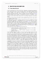
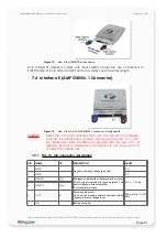
7.1 Interface A (16-pin Molex 43045-1609)
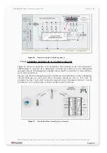
Figure 4:
View of the 16-pin Molex 43045-1609 connector pin assignments
7.1.1 Description of the 16-pin connector
PIN
NAME
I/O
DISCRIPTION
LEVEL
1
MIC N1
I(-)
3
MIC P1
I(+)
Balanced microphone input. Can be used to
directly feed an active microphone.
If not used leave it open.
R
I
≈ 50 kΩ differential
V
Imax
= 20 mVpp
2
Analog Input 2
I
4
Analog Input 1
I
General propose analog inputs.
up to 32 V DC/8 bit resolution
5
Out_2
O
7
Out_1
O
9
Out_3
O
11
Out_4
O
Open collector outputs.
300 mA max. at +10.8 .. +32V DC
6
Inp_4
I
8
Inp_3
I
10
Inp_2
I
12
Inp_1
I
13
IGN
I
General propose inputs.
HIGH ≥+10.8 .. +32 V DC
LOW = 0V
10.8 .. 32 V DC
14
BAT ON/OFF
I/O
Charging control pin which has to be pulled to
ground when the internal battery should be
charged, otherwise left it open.
Never onnect this pin to power supply (V+).
When pulled to GND the device starts
charging the battery, otherwise if its is
left open the device stops charging the
battery.
15
VC+
I
Power supply input (Input 7). The power
supply must be able to meet the requirements
of current consumption in a Tx burst (up to 2
A). Sending with two timeslots doubles the
duration of current pulses to 1154 µs (every
4.616 ms)!
V
I
= +10.8 ... +32.0 V
±
5 %
I
max
≤ 2 A (during Tx burst)
1 x Tx, peak current 577 µs every 4.616
ms
2 x Tx, peak current 1154 µs every 4.616
ms
16
GND
-
Negative operating voltage (ground).
0 V
Table 11:
Pin description of 16pin Molex connector
This confidential document is a property of FALCOM and may not be copied or circulated without previous permission
.
Page 31

