STEPPII-55/56-LT H
ARDWARE
DESCRIPTION
V
ERSION
1.01
CAUTION:
1) PLEASE, KEEP IN MIND THAT THE PIN (BATT ON/OFF) HAS IN NO CASE TO BE
CONNECTED NEITHER TO THE OPERATING VOLTAGE (V
VC+
) PIN NOR TO ANY
EXTERNAL POWER SOURCE.
2) CHARGING PROCESS CAN ONLY BE ACCOMPLISHED IN A TEMPERATURE
RANGE FROM 0 °C TO +40 °C, TYPICALLY 15 TO 25 °C.
THE EXTREME TEMPERATURES HAVE AN UNFAVOURABLE INFLUENCE ON THE
RECHARGEABLE BATTERIES. THE CAPACITY AND LIFE CYCLE OF THE BATTERIES
ARE REDUCED IF THEY ARE KEPT AT COLD OR WARM PLACES, E.G. IN A
CLOSED CAR AT SUMMER OR WINTER CONDITIONS. TRY ALWAYS TO KEEP THE
CONNECTED BATTERY (STEPPII-55/56-LT) AT NORMAL TEMPERATURES BETWEEN
15 °C AND 25 °C.
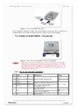
Figure 10:
BATT ON/OFF pin connection example.
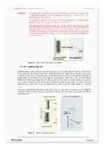
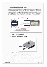
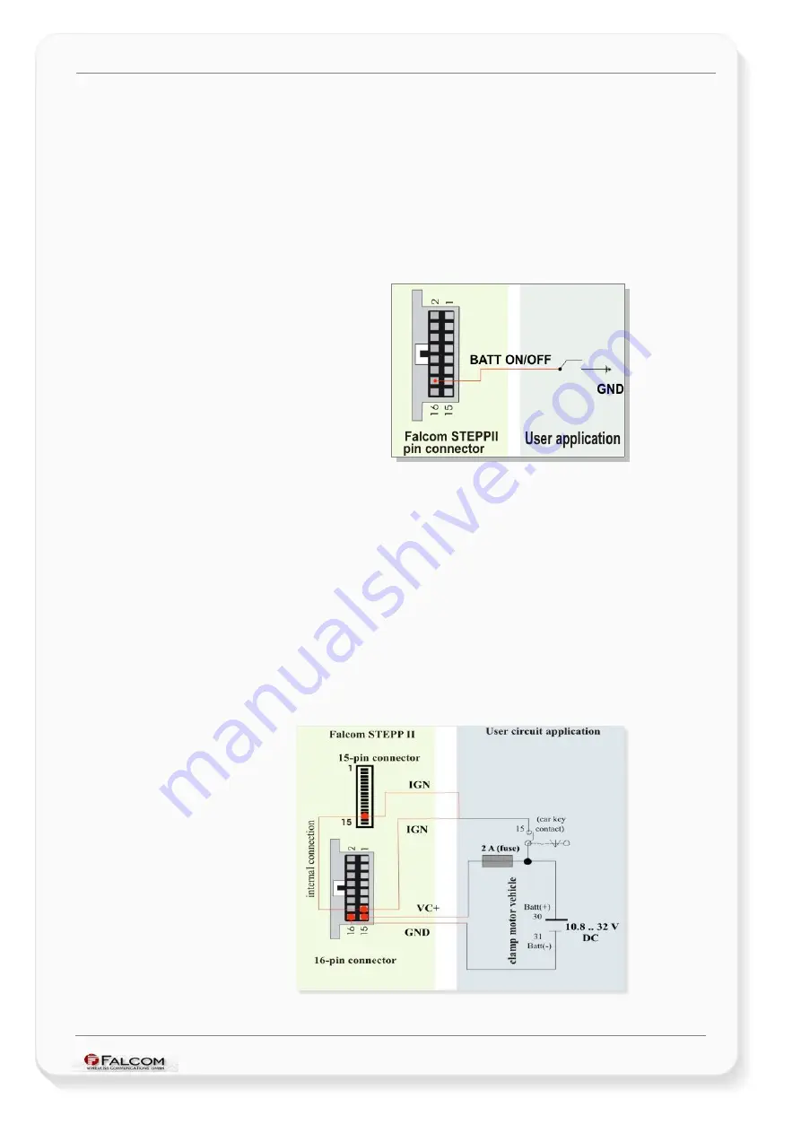
7.1.2.5 Ignition (pin 13)
STEPPII-55/56-LT provides two Ignition pins (pin 13) on the Molex and AMP connectors.
Their functionality is the same. The vehicle ignition line (starter lock clamp 15) can be
connected to one of the IGN pins of terminals (Pin 13). Thus, it is possible to send an
alarm SMS (by starting the car engine), prerequisite, the input IGN of the STEPPII-
55/56-LT should be configured for this purpose. Both pins 13 on the Molex connector
and AMP connector are internally connected with each other, so they can be
alternatively used. For more information see the corresponding figure in chapter
Note that the STEPPII-55/56-LT’s IGN pins are not assumed to switch on the STEPPII-
55/56-LT terminal, they are only input pins, which can be used for specific customer
requirements.
Figure 11:
Ignition connection example
This confidential document is a property of FALCOM and may not be copied or circulated without previous permission
.
Page 35

