STEPPII-55/56-LT H
ARDWARE
DESCRIPTION
V
ERSION
1.01
11 APPENDIX
11.1Schematics
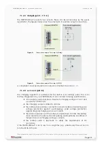
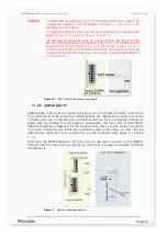
The figures below illustrate the recommended schematics for the connection of the
16-pin Molex and 15-pin AMP connectors.
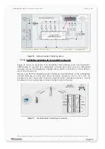
11.1.1 Installation guidance for 16-pin Molex connector
On the top of the schematic the corresponding pin out of the 16-pin Molex
connector can be found.
A general purpose terminal providing multiple digital and analogue inputs as well as
outputs for a variety of uses.
The STEPPII-55/56-LT comprises 7 inputs, 4 outputs and 2 analog inputs.
Of the 7 inputs, 4 inputs are free available for the user application. Three of the inputs
are predefined by the manufacturer as below:
-
1 x Power supply
→ which has to be connected to the vehicle battery
(clamp 30).
-
2 x Ignition lines
→ one from them can be connected to the vehicle
starter lock (clamp 15). It can be used to trigger an alarm SMS when
clamp 15 (ignition contact) of the vehicle is closed (engine of vehicle
started). These pins are not provided to switch ON/OFF the STEPPII-
55/56-LT terminal.
4 digital inputs can be used to trigger any alarm type (SMS, voice or data), i.e. they
can be connected to the car alarms or to a door switch, etc.
4 digital outputs are useful to switch remotely ON/OFF an external device. A
schematic below in this section shows how digital inputs/outputs can be used.
Note that all provided outputs have to be used on the same level to the operating
voltage (V
VC+
).
4 digital outputs are useful to switch remotely ON/OFF an external device. A
schematic below in this section shows how digital inputs/outputs can be used.
Note that, the outputs of the STEPPII-LT and VC+ must be on the same voltage level
when they operate.
STEPPII-LT device is not protected against over-voltage and over-current. The
operating voltage range must never be exceeded. The positive wire of the
STEPPII-LT (input power supply) must always be protected manually with a
2A fuse at +10.8 … +32 VDC. See circuit diagram below.
Please note that, all ground pins of the STEPPII-LT unit should be isolated from the
vehicle body to avoid ground loops.
CAUTION
IF YOU USE A GROUND-MOUNTED ANTENNA, TO AVOID ANY FAULT CURRENT
ENSURE THAT ANTENNA GROUND DOES NOT COME INTO CONTACT WITH
VEHICLE BODY. PLEASE, DOUBLE-CHECK ALL GROUNDS AND OTHER USED
LINES WHETHER THEY ARE ISOLATED FROM VEHICLE GROUND.
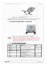
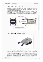
A microphone can be connected to pin 1 and pin 3 of the 16-pin Molex connector.
The figure 20 shows an example for the installation of the STEPPII-I/O’s in a motor
vehicle.
A microphone can be connected to pin 1 and pin 3 of the 16-pin Molex connector.
The figure 20 shows an example for the installation of the STEPPII-55/56-LT-I/O’s in a
motor vehicle.
This confidential document is a property of FALCOM and may not be copied or circulated without previous permission
.
Page 45


