background image

STEPPII-55/56-LT  H

ARDWARE


DESCRIPTION

V

ERSION

 1.01

7 HARDWARE INTERFACES

This chapter describes the hardware interfaces:

pinout on the 16-pin (Molex) connector

pinout on the 15-pin (AMP) connector

RF interfaces

SIM interface

LED’s indicator

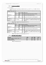
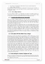
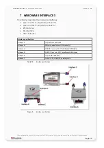
Interface specifications

Interface A

16-pin Molex 43045-1609

Interface B

SIM card reader for small SIM cards (3V)

Interface C

GPS RF Connector 50 

 Fakra/Radiall (SMB-Male)

Interface D

GSM RF Connector 50 

 Fakra/Radiall (SMB-Male)

Interface E

15-pin AMP 5-558556-1

Interface F

Optical LEDs, GSM/GPS operating state 

Table 10:

Interface specifications

Figure 3:

Interface specifications

This confidential document is a property of FALCOM and may not be copied or circulated without previous permission

.

Page 30

Summary of Contents for STEPPII-55-LT

Page 1: ...THIS DOCUMENT IS AVAILABLE AT HTTP WWW FALCOM DE STEPPII 55 56 LT Hardware description Version 1 01 Updated Tue 29 May 2007 ...

Page 2: ...T 15 4 1 1 Power consumption 16 4 1 2 Operating temperatures 16 4 2 BATTERY TECHNICAL DATA 17 4 3 TECHNICAL SPECIFICATIONS OF GSM GPRS ENGINE 18 4 3 1 Air interface of the STEPPII 55 56 LT GSM GPRS part 19 4 4 TECHNICAL SPECIFICATIONS OF GPS RECEIVER 21 4 5 NMEA DATA MESSAGE 22 5 FUNCTIONAL DESCRIPTION 23 5 1 HOW DOES IT WORK 23 5 2 FALCOM STEPPII 55 56 LT TYPICAL APPLICATIONS 24 6 STEPPII 55 56 L...

Page 3: ...tor description 37 7 4 2 Special pin description 38 7 4 2 1 VC 5 38 7 4 2 2 Boot select 38 7 4 2 3 Serial communication signals RxA TxA 38 7 4 2 4 Speaker outputs characteristics 39 7 5 INTERFACE F LED S DESCRIPTION 39 7 6 INTERFACE E MOUNTING HOLES 40 7 6 1 1 Mounting the cradle to the terminal 40 7 6 1 2 Placing the terminal 41 8 HOUSING 42 9 STEPPII 55 56 LT MOUNTING CRADLE 43 10 RF EXPOSURES 4...

Page 4: ...ase 23 02 2007 1 01 F Beqiri The operating voltage VVC and GND is protected from reverse pole connection as long no grounded antenna and or an AMP connector is NOT connected to the STEPPII see chapter 6 1 29 05 2007 This confidential document is a property of FALCOM and may not be copied or circulated without previous permission Page 4 ...

Page 5: ...wing Internet address http www falcom de Trademarks Some mentioned products are registered trademarks of their respective companies Copyright This documentation is copyrighted by FALCOM WIRELESS COMMUNICATIONS GmbH with all rights reserved No part of this documentation may be produced in any form without the prior written permission of FALCOM WIRELESS COMMUNICATIONS GmbH FALCOM Wireless Communicat...

Page 6: ... 850MHz GSM 1800 MHz and GSM 1900 MHz it supports also state of art GPS technology for satellite navigation The embedded firmware based on the eCos operating system for the TCP IP communication protocol TCP IP stack converts data streams into data packets and makes GPRS traffic possible for industrial and automotive applications No PDA or laptop is needed for establishing a GPRS connection It has ...

Page 7: ...re 12 parallel channel low power GPS core ARM7TDMI processor that controls all functions of the system Power Control circuitry with 850 mAh Li Ion backup battery Audio amplifier Interface circuitry Physical interfaces 16 pin Molex connector Type Molex 43045 1609 and counterpart Casing 43025 1600 and Box type spring contact 43031 0001 for power supply and I O s 15 pin AMP connector Type AMP5 558556...

Page 8: ...S 1900 MHz and is available to use in the American Networks Regarding the electrical interfaces mechanical specification dimension form etc and electrical specification are the same to all terminals Please note that according to your requirements you can choose the desired STEPPII LT device 1 4 Used abbreviations Abbreviation Description ASIC Application Specific Integrated Circuit DOP Dilution of...

Page 9: ... Data Circuit terminating Equipment interface for Short Message Service and Cell Broadcast Service 2 ETSI GSM 07 07 AT command set for GSM Mobile Equipment 3 ITU T V 25ter Serial asynchronous automatic dialing and control 4 SiRF binary and NMEA protocol specification 5 steppII_getting_started pdf 6 steppII_firmware_2 3 xx_manual pdf supporting GSM GPRS services 7 steppII_firmware_1 6 xx_manual pdf...

Page 10: ...purchaser client of the devices The seller does not cover the extra costs for the use of the devices The seller gives no recommendation for the use of specific SIM cards and does not liable also for the fact that the devices are usable with all available SIM cards The seller also covers no other costs that are needed for the application of the customer in connection with this device 2 2 Exposure t...

Page 11: ...rrent law 2 6 Electronic devices Most electronic equipment for example in hospitals and motor vehicles is shielded from RF energy However RF energy may affect some malfunctioning or improperly shielded electronic equipment 2 7 Vehicle electronic equipment Check your vehicle manufacturer s representative to determine if any on board electronic equipment is adequately shielded from RF energy 2 8 Med...

Page 12: ...odem in a vehicle powered by liquefied petroleum gas such as propane or butane ensure that the vehicle complies with the relevant fire and safety regulations of the country in which the vehicle is to be used 2 13Non ionizing radiation As with other mobile radio transmitting equipment users are advised that for satisfactory operation and for the safety of personnel it is recommended that no part of...

Page 13: ...or to any positive pole of supply voltage Do not disassemble the unit and modify the battery Immediately discontinue use of the battery if while using charging or storing the battery the battery emits an unusual smell feels hot or appears abnormal in any other way This confidential document is a property of FALCOM and may not be copied or circulated without previous permission Page 13 ...

Page 14: ...s and the standards and recommendations for the protection of public exposure to RF electromagnetic energy established by government bodies and professional organizations such as directives of the European Community Directorate General V in matters of radio frequency electromagnetic energy This confidential document is a property of FALCOM and may not be copied or circulated without previous permi...

Page 15: ... full charged Temperature Normal operation without connected battery 0 C to 55 C see chapter 4 1 2 for further details Evaluation kit The STEPPII 55 56 LT Eval Board is designed to test evaluate and make basis configuration to enable remote monitoring configuration of the FALCOM STEPPII 55 56 LT It provides a sample configuration for application Physical characteristics Size 55 0 0 15 mm x 80 0 0 ...

Page 16: ...nsumption at 12 V DC Average current at 24 V DC GPS GSM on Operating with firmware 1 6 2 850 1800 1900 MHz GSM band 75 75 mA in idle mode base station sends at 85 dBm 111 93 mA in transmit mode at power level 7 3 119 103 mA in transmit mode at power level 5 0 maximum GPS GPRS on Operating with firmware 2 X XX To be defined mA in receive mode at maximum power level 5 3 x downstream 2 x upstream usi...

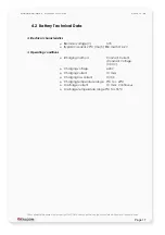
Page 17: ...g conditions Charging method Constant Current Constant Voltage CCCV Charging voltage 4 20V Charging current 1C max Charging low current C 100 Charging temperature range 0 C to 40 C Discharge current 1C max continuous Discharge temperature range 0 C to 55 C This confidential document is a property of FALCOM and may not be copied or circulated without previous permission Page 17 ...

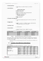
Page 18: ...upports two protocols PAP Password Authentication Protocol and CHAP Challenge Handshake Authentication Protocol commonly used for PPP connections Supports of Packet Switched Broadcast Control Channel PBCCH allows you to benefit from enhanced GPRS performance when offered by the network operators CSD CSD transmission rates 2 4 4 8 9 6 14 4 kbps non transparent V 110 Unstructured Supplementary Servi...

Page 19: ... 31 2 kbps 62 4 kbps CS 4 21 4 kbps 42 8 kbps 85 6 kbps Table 5 Coding schemes and maximum net data rates over air interface Please note that the values listed above are the maximum ratings which in practice are influenced by a great variety of factors primarily for example traffic variations and network coverage Please note that not all features given above in this chapter are utilized in our fir...

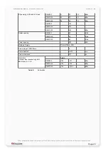
Page 20: ...5 MHz GSM 1900 80 MHz Carrier spacing 200 kHz Multiplex Duplex TDMA FTDMA FDD Time slots per TDMA frame 8 Frame duration 4 615 ms Time slot duration 577 µs Modulation Receiver input sensitivity ARP BER Class II 2 4 GMSK GSM 850 102 107 dBm GSM 1800 102 106 dBm GSM 1900 102 105 5 dBm Table 6 Air Interface This confidential document is a property of FALCOM and may not be copied or circulated without...

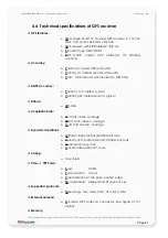
Page 21: ...city 0 05 meters second typical Datum WGS 84 Acquisition Rate Hot start 8 sec average Warm start 38 sec average Cold start 45 sec average Dynamic Conditions Altitude 18 000 meters 60 000 feet max Velocity 515 meters second 1000 knots max Acceleration 4 g max Jerk 20 meters second max Casing Fully shield Time 1 PPS Pulse Level CMOS Pulse duration 100 ms Time reference At the pulse positive edge Mea...

Page 22: ...tion GGA Time position and fix type data GLL Latitude longitude UTC time of position fix and status GSA GPS receiver operating mode satellites used in the position solution and DOP values VTG The number of GPS satellites in view satellite ID numbers elevation azimuth and SNR values GSV The number of GPS satellites in view satellite ID numbers elevation azimuth and SNR values RMC Time date position...

Page 23: ... vehicle starter lock clamp 15 To use the STEPPII 55 56 LT you need to insert a SIM card available for SMS data and voice calls The different services i e Voice Data and SMS depend on your application and to install the terminal indoor at the supposed location e g vehicle boat etc STEPPII 55 56 LT comes with a combined GSM GPS antenna To achieve an accurate geographical location of STEPPII 55 56 L...

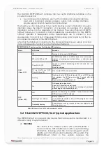
Page 24: ...ed to network monitoring control channels and user interactions No call in progress 75 ms On 75 ms Off 75 ms On 3 ms Off One or more GPRS contexts activated Flashing Flashing Indicates GPRS data transfer When a GPRS transfer is in progress the LED goes on within 1 second after data packets were exchanged Flash duration is approximately 0 5 s On On Depending on type of call Voice call Connected to ...

Page 25: ...ition Speed Course Temperature Remote reading Alarm Movement Fire Gas Water level and many others SETTING ALARM INPUTS For each input several telephone numbers destination numbers can be configured Beside the destination number alarm text as SMS with the desired GPS protocol max 2 protocols can be configured The alarm type could also be voice and data connection REMOTE MONITORING Normally the GPS ...

Page 26: ...d monitor STEPPII 55 56 LT devices as well as to set and poll the configuration remotely via SMS data call or over Internet form a remote server The software comprises a set of word like commands termed PFAL Each of these causes the terminal STEPPII 55 56 LT either to take a particular action or to read set a particular configuration The software provides the basic configuration settings needed wh...

Page 27: ...omponents such as digital outputs and handsfree set do not operate only from the external battery These components are operational as long as the main power VVC is applied to the STEPPII 55 56 LT terminal 6 1 1 Power up down scenarios In general be sure not to turn on the STEPPII 55 56 LT terminal module while it is out of the operating range of voltage and temperature stated in Table 11 and Table...

Page 28: ... point 6 2 Automatic GPRS Multislot Class change Temperature control is also effective for operation in GPRS Multislot class 10 If the board temperature exceeds the specified limit see 4 1 2 for temperature limits known as restricted operation while data are transmitted over GPRS the module automatically reverts from GPRS Multislot class 10 3 RX x 2 TX to class 8 4 RX x 1 TX This reduces the power...

Page 29: ...ns for DCE DTE connections it communicates with the customer application DTE using the following signals STEPPII 55 56 LT Terminal DCE to Application DTE RxA TXD TxA RXD Table 9 The signalling definitions between DTE and DCE This confidential document is a property of FALCOM and may not be copied or circulated without previous permission Page 29 ...

Page 30: ...ace A 16 pin Molex 43045 1609 Interface B SIM card reader for small SIM cards 3V Interface C GPS RF Connector 50 Ω Fakra Radiall SMB Male Interface D GSM RF Connector 50 Ω Fakra Radiall SMB Male Interface E 15 pin AMP 5 558556 1 Interface F Optical LEDs GSM GPS operating state Table 10 Interface specifications Figure 3 Interface specifications This confidential document is a property of FALCOM and...

Page 31: ...8 32 V DC 14 BAT ON OFF I O Charging control pin which has to be pulled to ground when the internal battery should be charged otherwise left it open Never onnect this pin to power supply V When pulled to GND the device starts charging the battery otherwise if its is left open the device stops charging the battery 15 VC I Power supply input Input 7 The power supply must be able to meet the requirem...

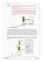
Page 32: ...ature sensor a NTC resistor for instance It is possible to set a low temperature alarm and a high temperature alarm upper and lower values passed to required temperature Passage through these thresholds will trigger an alarm We recommend to use SMS as alarm type with the protocol GPIOP SMS including voltage values and text It depends on the user configuration The SMS can be received on a mobile ph...

Page 33: ...are high active so they can be connected to 10 8 32 V DC The figure below illustrates how to connect these inputs If one of the connected pins inputs is activated for at least 1 sec STEPPII 55 56 LT will release an alarm SMS Voice or data connection The alarm type and the alarm text alarm type SMS depend on the configuration done by the user The inputs can be configured by using the configuration ...

Page 34: ... Li Ion battery pack specifies a maximum charging voltage of 4 2 V and a capacity of 850 mAh The charging current is limited to 450 mA The battery incorporates a protection circuit capable of detecting over voltage protection against overcharging under voltage protection against deep discharging and over current The internal resistance of the battery is smaller then 150 mΩ The battery cell is inse...

Page 35: ... 13 STEPPII 55 56 LT provides two Ignition pins pin 13 on the Molex and AMP connectors Their functionality is the same The vehicle ignition line starter lock clamp 15 can be connected to one of the IGN pins of terminals Pin 13 Thus it is possible to send an alarm SMS by starting the car engine prerequisite the input IGN of the STEPPII 55 56 LT should be configured for this purpose Both pins 13 on ...

Page 36: ... The GSM RF connector has an impedance of 50 Ω A GSM antenna can be directly connected to this connector The other left one is provided for GPS RF connection The GPS RF connector see figure below has an impedance of 50 Ω Active antennas have an integrated low noise amplifier They can be directly connected to this connector The integrated low noise amplifier of the antenna is internally supplied wi...

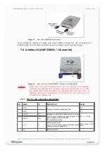
Page 37: ... THE ADAPTER INTO THE AMP SLOT OF TERMINAL REMOVE IT IMMEDIATELY AND CHECK FOR ANY DAMAGE OF ITS CONNECTOR OR BEND PINS 7 4 1 The 15 pin connector description PIN NAME I O DISCRIPTION LEVEL 1 GND 2 GND Negative operating voltage grounds 0 V 0 V 3 SPK N1 O 4 SPK P1 O Analogue audio interface Balanced audio output Can be used to operate directly an earpiece This audio interface is without amplifier ...

Page 38: ...h require 100 mA at 5 V 5 VDC This power supply is available when the terminal is switched on To use this pin see chapter 11 1 2 7 4 2 2 Boot select To update a new STEPPII 55 56 LT firmware this pin should be switched to GND ground Leave it open for a normal STEPPII 55 56 LT operation tracking call etc 7 4 2 3 Serial communication signals RxA TxA The board supports a full duplex serial channel Th...

Page 39: ... s description The actual state of the STEPPII 55 56 LT is displayed by two LED s on the interface D of the terminal The following description shows the function of these LED s Figure 15 View of the GSM GPS LED s Two LEDs show the actual state of the STEPPII 55 56 LT terminal Red Battery Battery status and ambient temperature about its functionality see Table 8 Green GSM GSM network status about i...

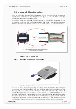
Page 40: ...7 6 1 1 Mounting the cradle to the terminal Figure 17 Attached cradle to the terminal In order to avoid any damage during mounting place the terminal if needed on the cradle and push it up down until you see both terminal and cradle holes are facing each other Screws must be inserted with the screw head on the bottom of cradle through to the provided holes on the bottom of the STEPPII 55 56 LT Use...

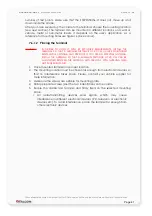
Page 41: ...A SO THAT A MINIMUM DISTANCE OF 20 CM CAN BE MAINTAINED BETWEEN THE ANTENNA AND PERSONS WITH ANTENNA GAIN NOT EXCEEDING 3 DBI 1 Place mounted terminal in a proper location 2 The mounting location must be chosen far enough from electronic devices so that no interference takes place Please contact your vehicle supplier for more information 3 Make sure the screws are suitable for mounting plate 4 Dri...

Page 42: ...N 1 01 8 HOUSING The housing material Galvano ABS gloss chromium plated Figure 18 Housing of the STEPPII 55 56 LT This confidential document is a property of FALCOM and may not be copied or circulated without previous permission Page 42 55 80 25 ...

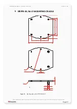
Page 43: ...II 55 56 LT MOUNTING CRADLE Figure 19 Mounting cradle of the STEPPII 55 56 LT This confidential document is a property of FALCOM and may not be copied or circulated without previous permission Page 43 25 30 80 49 55 75 O 2 5 O 3 O 2 4 O 4 2 O 6 R0 5 R1 R66 25 ...

Page 44: ... Modifications not expressly approved by this company could void the user s authority to operate the equipment Statement according to FCC part 15 105 NOTE This equipment has been tested and found to comply with the limits for a Class B digital device pursuant to Part 15 of the FCC Rules These limits are designed to provide reasonable protection against harmful interference in a residential install...

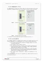
Page 45: ...w digital inputs outputs can be used Note that all provided outputs have to be used on the same level to the operating voltage VVC 4 digital outputs are useful to switch remotely ON OFF an external device A schematic below in this section shows how digital inputs outputs can be used Note that the outputs of the STEPPII LT and VC must be on the same voltage level when they operate STEPPII LT device...

Page 46: ... amplifier allows direct connection of a Hands Free set to Pin 9 and Pin 10 Please note that the integrated audio interfaces are predefined on the embedded internal firmware as voice and alarm channels where by pins 7 8 9 and 10 provided on the 15 pin AMP connector support voice channel and pins 1 and 3 provided on the 16 pin Molex connector support alarm channel Figure 21 Possible installation fo...

Page 47: ...M STEPPII 55 56 LT 15 pin connector FALCOM STEPPII 55 56 LT will automatically answer an incoming call after the second or third ring Alarm channel The alarm channel allows you to establish a voice call listen in mode to the FALCOM STEPPII 55 56 LT without activating the loudspeaker interface on the FALCOM STEPPII 55 56 LT In this case connect a Hands Free microphone to pins 1 and 3 of the FALCOM ...

Reviews: