STEPPII-55/56-LT H
ARDWARE
DESCRIPTION
V
ERSION
1.01
7.6 Interface E (Mounting holes)
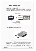
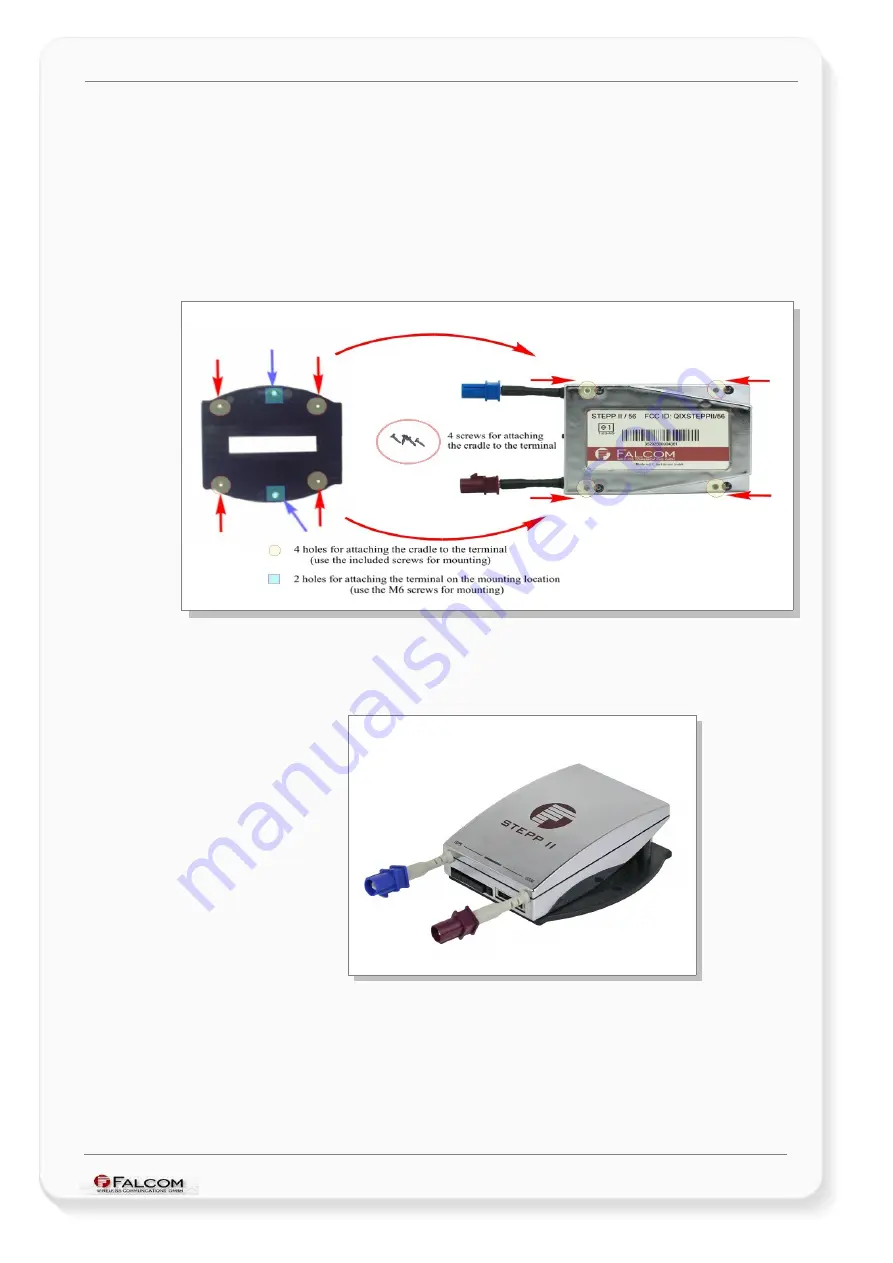
The STEPPII-55/56-LT compact terminal provides 4 holes for attaching it to the suitable
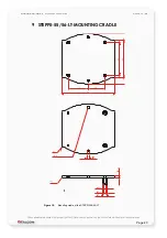
cradle. As a reference for mounting holes use figure 16 below in this section. The
cradle is available in the sales package.
In order to avoid any damage during mounting of the terminal is required to use
(choose if the screws are damaged) properly the screws delivered with STEPPII-
55/56-LT. Fasteners are 22 x 6 mm screws plus suitable washers, or customized screws.
Figure 16:
View of the mounting holes
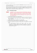
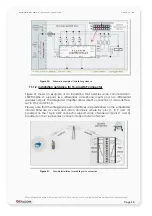
7.6.1.1 Mounting the cradle to the terminal
Figure 17:
Attached cradle to the terminal.
In order to avoid any damage during mounting, place the terminal (if needed) on
the cradle and push it up/down until you see both terminal and cradle holes are
facing each other. Screws must be inserted with the screw head on the bottom of
cradle through to the provided holes on the bottom of the STEPPII-55/56-LT. Use a
suitable screwdriver to perform the rotation. Screw up kindly the appropriate screws.
To avoid short circuits ensure that the customized screws (screws with different
length) do not come into contact with the STEPPII-55/56-LT PCB since there are a
This confidential document is a property of FALCOM and may not be copied or circulated without previous permission
.
Page 40


