4-Channel Digital Video Recorder
5
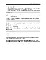
To reset the unit, you will need a straightened paperclip:
1.
Turn the DVR off.
2.
Poke the straightened paperclip into the unlabeled hole to the left of the Network port, and turn the DVR on.
3.
Hold the reset switch until the DVR turns on and live monitoring screen appears.
4.
Release the reset switch. All of the DVR’s settings are now at the original settings it had when it left the factory.
Network Port
The DVR can be networked using the 10/100Mb Ethernet connector. Connect a Cat5 cable with an
RJ-45 jack to the DVR connector. The DVR can be networked with a computer for remote monitoring,
searching, configuration and software upgrades. See
Chapter 3
─
Configuration
for configuring the
Ethernet connections.
CAUTION: The network connector is not designed to be connected directly with cable or wire
intended for outdoor use.
Audio In/Out
Your DVR can record audio from up to four sources. Connect the audio sources to
Audio In
1
,
Audio In 2
,
Audio In 3
and
Audio In 4
as needed using RCA jacks. Connect
Audio Out
to your amplifier.
NOTE: It is the user’s responsibility to determine if local laws and regulations permit
recording audio.
NOTE: The DVR does not have amplified audio output, so you will need a speaker with an amplifier. The DVR
does not have a pre-amplifier for audio input, so the audio input should be from an amplified source, not directly
from a microphone.
Power Cord Connector
Connect the AC power cord to the DVR and then to a wall outlet.
WARNING: ROUTE POWER CORDS SO THAT THEY ARE NOT A TRIPPING HAZARD. MAKE
CERTAIN THE POWER CORD WILL NOT BE PINCHED OR ABRADED BY FURNITURE. DO NOT
INSTALL POWER CORDS UNDER RUGS OR CARPET.
THE POWER CORD HAS A GROUNDING PIN. IF YOUR POWER OUTLET DOES NOT HAVE A
GROUNDING PIN RECEPTACLE, DO NOT MODIFY THE PLUG. DO NOT OVERLOAD THE CIRCUIT
BY PLUGGING TOO MANY DEVICES IN TO ONE CIRCUIT.
Your DVR is now ready to operate. Refer to
Chapter 3
─
Configuration
and
Chapter 4
─
Operation
.
Summary of Contents for 4-Channel
Page 1: ......
Page 2: ......
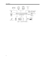
Page 10: ...User s Manual 2 Figure 1 Typical DVR installation...
Page 14: ...User s Manual 6...
Page 50: ...User s Manual 42...


