background image

21

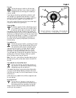
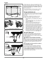
ArtNo.342-0005 - 90SC Induction - Drawer position

ArtNo.341-0003 - Drawer locking

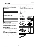
Repositioning the Cooker following 

Connection

If you need to move the cooker once it has been connected, 
make sure it is isolated at the electrical supply before 
gripping under the fascia panel and lifting the front of the 
cooker slightly 

(Fig.7-16)

. Check behind the cooker to ensure 

that the electricity cable is not caught. As you progress, 
always ensure that the cable has sufficient slack to allow the 
cooker to move.

If a stability chain is fitted, release it as you ease the cooker out. 
Do not forget to refit it when you replace the cooker.

When you replace the cooker, check behind it again once 
more to ensure that the electricity cable is not caught or 
trapped.

Hob Check

Check each cooking zone in turn. Be sure to use pans of the 
correct size and material.

Oven Check

Turn on the ovens. Check the oven fans start to turn and that 
the ovens heat up.

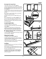
Fitting the Plinth

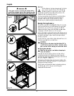
Remove the 3 screws for the plinth mounts along the front 
bottom edge of the range 

(Fig.7-17)

. Fasten the plinth using 

these screws (alternative colour screws can be found in the 
loose parts pack).

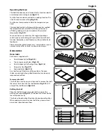
Refitting the Drawer

Replace the drawer by locating it on the side runners and 
pushing in.

To refit the drawer, pull the side rails fully out. Carefully move 
the drawer back between the rails and rest it on the side rails.

At each side, hold the front of the drawer and pull the side 
rail forward so that the clips click into position, holding the 
drawer to the side rails 

(Fig.7-18)

.

Refitting the Oven Door

To refit the door, slide the hinges back into their slots. Rotate 
the locking ‘U’ clips back to fit onto the hinges.

Customer Care

Please complete your details in this Guide, inform the user 
how to operate the cooker and hand over the Instructions.

Thank you

ArtNo.000-0012 - Securing the plinth

Fig.7-17

Fig.7-18

ArtNo.010-0009 Pushing the cooker

Fig.7-16

English

Summary of Contents for 900S Dual Fuel

Page 1: ...900S Induction ArtNo 000 0008 Falcon logo shaded User Guide Installation Service Instructions U109999 04...

Page 2: ...Table 14 6 Troubleshooting 15 Contents 7 Installation 17 Dear Installer 17 Safety Requirements 17 Location of Cooker 17 Positioning the Cooker 18 Unpacking the Cooker 18 Moving the Cooker 18 Completi...

Page 3: ...s on or use the cooker for a long time open a window or turn on an extractor fan Personal Safety Important information for pacemaker and implanted insulin pump users The functions of this hob comply w...

Page 4: ...ms on the hob when it is not is use e g tea towels frying pans containing oil DO NOT place plastic or aluminium foil or plastic containers on the hob DO NOT leave the hob zones switched on unless bein...

Page 5: ...t suitable for use with an induction hob so please check carefully before purchasing any cookware Pans made of copper aluminium or ceramic are not suitable for use on an induction hob The kind of pan...

Page 6: ...l and DO NOT RELY on the pan detector If a cooking area is switched on and there is no pan in place or if the pan is too small for the cooking area then no heat will be generated The symbol will appea...

Page 7: ...hob turn together induction controls 2 and 4 simultaneously anti clockwise for approximately 3 seconds until L appears in the hob control display for all cooking areas This will NOT a ect the oven it...

Page 8: ...careful eye on your cooking until you are familiar with each function Fig 2 7 Remember not all functions will be suitable for all food types Multi function oven modes Defrost This function operates th...

Page 9: ...ion ideal for cooking large items that need thorough cooking such as a large meat roast It is also possible to bake on two racks at one time although they will need to be changed over during the cooki...

Page 10: ...when a function is selected All oven functions are available in full and divided forms and shelves are provided for use in both forms WARNING Take great care when removing the divider NOT to scratch t...

Page 11: ...d types Please remember that all ranges vary temperatures in your new ovens may di er to those in your previous range Accessories Oven racks Each oven is supplied with One full capacity shelf Fig 2 14...

Page 12: ...lammable materials may explode and result in re or property damage To remove the drawer pull it fully forward Fig 2 23 Lift up the ends of the plastic clips one each side to release the catches holdin...

Page 13: ...han necessary otherwise the knobs may get very hot Always leave a fingers width between dishes on the same shelf This allows the heat to circulate freely around them To reduce fat splashing when you a...

Page 14: ...35 minutes individual 10 20 minutes 15 20 minutes 15 20 minutes per 500g Steaks according to thickness 45 50 minutes per 500g of mixture 2 2 hours Up to 3 hours 80 90 minutes 15 25 minutes 10 15 minut...

Page 15: ...the cooking surface As a nal step wipe the cooking surface with a clean dry paper towel Cleaning Spills For spills and boil overs that occur while cooking turn the unit o and wipe the area surroundin...

Page 16: ...e Cast iron Remove rust and food debris with a well soaped steel wool pad along the grain Rinse and allow to dry Apply a proprietary sealed hotplate restorer Electrical Retailers to restore colour and...

Page 17: ...n When cooking foods with a high water content e g oven fries there may be some steam visible at the rear grille Take care when opening the oven door as there may be a momentary pu of steam when the o...

Page 18: ...Oven temperature getting hotter as the cooker gets older If turning the knob down has not worked or only worked for a short time then you may need a new thermostat This should be tted by a service pe...

Page 19: ...omplete the cooker installation satisfactorily Multimeter for electrical checks Cooker levelling tool with Allen keys provided in pack Stability bracket 7 Installation You will also need the following...

Page 20: ...tween units to allow for moving the cooker If a ush t is required t the cooker up to the unit at one side then t the unit the other side Do not box the cooker in it must be possible to move the cooker...

Page 21: ...corners of the cooker Completing the Move Unfold the rear edge of the pack base tray Grip under the fascia panel and lift the front of the cooker slightly Fig 7 8 Carefully push the cooker backwards o...

Page 22: ...Measure the height from oor level to engagement edge in back of cooker Add 3mm to this dimension and assemble the stability bracket to this height i e from oor level to underside of the top member an...

Page 23: ...Turn on the ovens Check the oven fans start to turn and that the ovens heat up Fitting the Plinth Remove the 3 screws for the plinth mounts along the front bottom edge of the range Fig 7 17 Fasten the...

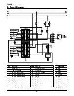
Page 24: ...ht hand fan element G Right hand fan H Cooling fan I Left hand bottom element J Left hand top element outer K Left hand top element inner Colour Code bl Blue br Brown bk Black or Orange r Red v Violet...

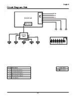
Page 25: ...53 90 induction 900S circuit diagram Circuit Diagram Hob Code Description 1 Left hand front element 2 Left hand back element 3 Right hand back element 4 Right hand front element 5 Centre element Colou...

Page 26: ...Non boost Boost Fan element 3 31 kW 1 65 kW Left hand front 1 40 kW 1 80 kW Top element 3 49 kW 1 75 kW Left hand back 1 85 kW 2 50 kW Browning element 2 11 kW 1 06 kW Centre 2 30 kW 3 20 kW Bottom el...

Page 27: ...o the rest of this booklet especially the Troubleshooting section rst to check that you are using the appliance correctly If you are still having di culty contact your retailer 10 Warranty After Sales...

Page 28: ...26...

Page 29: ...ArtNo 000 0003 CE logo ArtNo 000 0001 Aga address block...

Reviews: