background image

32

WARNING  SERVICING TO BE CARRIED OUT ONLY BY AN AUTHORISED PERSON

Disconnect from electricity before servicing. Check appliance is safe when you have finished. 

3.  To Remove Side Panels

Disconnect from electricity supply.

Remove the Control Panel - see 1. Pull the cooker forward. 
Remove the 4 retaining screws for each panel (1 at the front 
base, 1 on the top and 2 at the rear). 

Reassemble in reverse order.

4.  To Remove Ignition or light Switch

Remove the Control Panel - see 1.

NB. The old switch may be destroyed during removal. 
Remove the old switch from its bezel by griping the switch 
body behind the control panel and twisting sharply. The 
switch bezel can then be removed by folding back its 
locking wings and pushing forward. Fit the new bezel to the 
control panel by fi rst lining up the raised key on its body 
with the cutout in the control panel and pushing it in from 
the front. Assemble the new switch to the bezel by lining up 
the key sections and pushing home. Fit the new button by 
pushing in from the front. 

Replace Control Panel in reverse order and test for ignition.
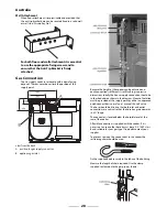
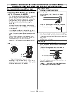
5.  To Remove Clock

Disconnect from electricity supply.

Remove the Control Panel (See 2). Pull off  the timer control 
button(s).

Remove the timer/mounting bracket assembly from the 
control panel by removing the fi xing screws. 

Remove the timer from its mounting bracket by depressing 
the plastic lugs on the timer case, at the same time pulling 
the unit forward.

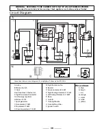
Reassemble in reverse order. When replacing leads refer to 
the wiring diagram. Check operation of timer.

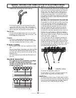
BEFORE SERVICING ANY GAS CARRYING COMPONENTS 
TURN OFF GAS SUPPLY.

6. To 

Remove 

Thermostat

Remove control panel and appropriate hotplate tray. Open 
oven door. Remove oven furniture. For RH oven, remove 
thermostat phial cover (2 screws).

Unclip the thermostat phial from the clips in the oven back.

For LH oven pull cooker forward to gain access to the cover 
box at the rear of the cooker. Remove the four screws 
securing the cover and lift clear.

Feed the thermostat capillary out of the oven. Disconnect 
wiring from thermostat. Remove 2 screws holding 
thermostat to mounting panel. Fit new thermostat and 
reassemble in reverse order. Ensure that the phial is clipped 
to the oven back with the phial centrally positioned 
between the clips.

Check operation of thermostat.

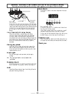
7.  To Change Grill Controller

Remove the control panel (see 2) and LH hotplate tray. 
Disconnect wiring from controller. Remove 2 screws holding 
controller to mounting panel. Fit new controller and 
reassemble in reverse order. Check for correct operation.

8. To 

Change 

Control 

Taps

Remove the Control Panel (see 1). Lift up the appropriate 
hotplate tray front (see 2).

Undo compression fi tting at the rear of the tap. Remove the 
fi xings that secure the tap to the gas rail. Remove the tap. 
Remove and discard the gasket seal. Fit new gasket seal to 
replacement tap. Re-assemble in reverse order. Check the 
appliance is gas sound. Check hotplate ignition.

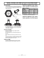
9.  To Change Hotplate Burner Injector

Remove burner cap and head. Remove old jet. Fit new 
injector. Reassemble in reverse order. Check appliance is gas 
sound.

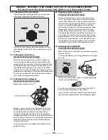
10. To Change Hotplate Burner Electrode

Lift off  pan supports, remove burner cap. Remove the 
screw holding the electrode. Pull electrode vertically up 
suffi

  ciently to grip the lead between thumb and forefi nger. 

Pull off  the electrode, but keep hold of the lead. Fit new 
electrode to the lead. Fix electrode in burner with screw. 
Replace burner cap. Check the burner ignition. Replace pan 
supports.

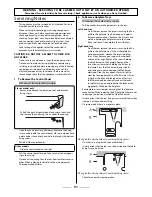
11. To Remove or Change a Hotplate Burner.

Remove the hotplate tray (see 2).

LH hotplate burners

Remove heat shield (2 screws). The burners are mounted 
in 2’s on cross supports. Disconnect the burner feed pipes 
at the burners. Remove the screw on the right holding 
the cross support. Slide the support to the right to release 
in from the left hand location. Lift the cross support and 
burners clear. The burners are fi xed to the cross supports 
with 2 screws. Remove the appropriate burner and fi t 
the new one. Reassemble in reverse order. Check burner 
operation is satisfactory.

RH Wok burner

Disconnect the burner feed pipes at the burner. Fit the 
new one and reassemble in reverse order. Check burner 
operation is satisfactory.

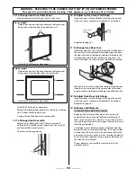
12. To Remove an Oven Door

Open oven door. Support the door and remove the two 
screws securing the upper hinge and gasket to the cooker 
front. Remove the door from the lower hinge by lifting 
slightly and moving outwards.

Reassemble in reverse order.

13. To Change Ignition Generator

Disconnect from electricity supply.

Pull cooker forward to gain access to the cover box at the 
rear of the cooker. Remove the screws securing the cover 
and lift clear. Pull off  all the leads to the generator noting 
their positions. Slacken the two screws holding generator to 
cooker and remove generator.

Fit new generator to cooker and replace leads. Reassemble 
in reverse order. Refer to wiring diagram. Check ignition 
performance.

Summary of Contents for Classic 110 Dual Fuel

Page 1: ...110 Dual Fuel 110 Dual Fuel Professional 110 Dual Fuel Falcon 110 Dual Fuel Users Guide Installation Service Instructions Australia U108600 01...

Page 2: ...Gas and Electricity on Make sure that the gas supply is turned on and that the cooker is wired in and switched on The cooker needs electricity Peculiar smells When you rst use your cooker it may give...

Page 3: ...10 Oven shelves Page 10 The Handyrack Page 11 Oven light Page 11 The Browning Element Page 11 Storage Page 11 Moving your cooker Page 12 Oven cooking guide Page 13 Cleaning your cooker Page 14 Trouble...

Page 4: ...l reduce burner performance and could damage the pan supports 5 Avoid using unstable and misshapen pans that may tilt easily and pans with a very small base diameter e g milk pans single egg poachers...

Page 5: ...small ame symbol 5 Always leave space around the griddle for the gases to escape Never t two griddles side by side Large pans should also be spaced well apart The maximum pan base diameter is 250mm U...

Page 6: ...ted Turn the knob to position 3 4 For best results preheat for 2 minutes with the grill pan in position After placing your food on the grill pan grid slide the grill pan onto the side supports Adjust...

Page 7: ...nd element de ector when placing or removing items from the oven 2 The Right hand Fan Oven The fan in the right hand oven circulates hot air continuously which means faster more even cooking The recom...

Page 8: ...tart and stop the oven automatically Before you set the clock you must have two numbers clearly in mind The cook period which is the period of time you want the oven to cook The stop time which is the...

Page 9: ...he oven ovens rst Then you can adjust either of them manually in the normal way You can set the oven to turn on any time over the following 24 hour period If you want to cook more than one dish choose...

Page 10: ...around a roast dry them thoroughly or brush lightly with cooking oil Su cient heat rises out of the oven while cooking to warm plates in the grill compartment If you want to brown the base of a pastr...

Page 11: ...ing the other side out to clip it onto the other bracket Oven light Press the appropriate button to turn on one of the oven lights If one of the oven lights fail turn o the power supply before you cha...

Page 12: ...e oven a bit at a time checking behind it to make sure the gas hose is not caught Make sure both electricity and gas cables have su cient slack to move the cooker forward as you go along If a stabilit...

Page 13: ...2 3 190 C 15 20mins per 500g 15 20mins Turkey 160 C 2 150 C 20 25mins per 500g 20 25mins 200 C 2 190 C 15 20mins per 500g 15 20mins Stu ed Poultry Cook at 200 C or at 200 C for 20mins then 160 C for r...

Page 14: ...r on your cooker Recommended cleaning materials are shown in the table at the end of this section If you want to move your cooker for cleaning see the section called Moving your cooker All parts of th...

Page 15: ...forward to gain access to the sides see the Moving the cooker section of these instructions Open the oven door slightly and remove the front panel xing screws from the door sides two each side stainl...

Page 16: ...m soapy water Do not use abrasive cleaners on lettering Control Knobs Handles Plastic Chrome Warm soapy water soft cloth Oven Door Glass Glass Lid Toughened glass Hot soapy water cream cleaner scourer...

Page 17: ...om the oven When cooking foods with a high water content e g oven chips there may be some steam visible at the rear grille Take care when opening the oven door as there may be a momentary pu of steam...

Page 18: ...Oven not coming on when turned on manually Is the power on Is the clock illuminated If not there may be something wrong with the power supply Is the cooker supply on at the isolator switch Is the cloc...

Page 19: ...to cool and then switch o at the mains and before cleaning or carrying out any maintenance work unless speci ed otherwise in this guide All parts of the cooker become hot with use and will retain hea...

Page 20: ...eating of foods when frying at high or medium high temperatures Never try to move a pan of hot fat especially a deep fat fryer Wait until the fat is cool When the grill is on do not use the top of the...

Page 21: ...kely event that you have a problem with your appliance please refer to rest of this booklet especially the problem solving section rst to check that you are using the appliance correctly If you are st...

Page 22: ...tallation please complete the details BELOW If your customer has a problem relating to your installation they will be able to contact you easily Thank you Installer s Name Installer s Company Installe...

Page 23: ...See the data badge This appliance can be converted for use on Propane This appliance is designed for domestic cooking only Use for any other purpose could invalidate any warranty or liability claim Ve...

Page 24: ...ed the following tools 1 Electric drill 2 Masonry drill bit only required if tting the cooker on a stone or concrete oor 3 Rawlplugs only required if tting the cooker on a stone or concrete oor 4 Stee...

Page 25: ...aterial to the surface and covering with sheet metal with a minimum thickness of 0 4mm to a height C of not less than 150 mm above the hotplate should satisfy this requirement 3 Side clearances Measur...

Page 26: ...ller at both the front bottom corners of the cooker Unfold the rear edge of pack base tray Carefully push the cooker backwards out of the base pack Push the cooker close to its nal position leaving ju...

Page 27: ...s of the control panel and x the front handrail in position Anti Tip Device WARNING An anti Tip bracket and chain should be tted when the cooker is connected to a exible gas supply Unless properly ins...

Page 28: ...ns Ideally the house supply connection should be in the shaded area shown in the diagram Means of isolation must be provided at the supply point by either an approved quick connect device or a Type 1...

Page 29: ...right remove storage drawer The cooker is preset for a single phase earthed electrical connection It is essential to install a multi pole circuit breaker that completely disconnects the appliance from...

Page 30: ...long the front bottom edge of the cooker Hook the central keyhole over the central screw Twist and t each end keyhole over their respective screws Tighten the xing screws Oven Light Press the oven lig...

Page 31: ...care not to damage or strain the wiring Disconnect the wiring from the rear Reassemble in reverse order When replacing leads refer to the wiring diagram Check operation of timer 2 To Remove Hotplate...

Page 32: ...nel see 2 and LH hotplate tray Disconnect wiring from controller Remove 2 screws holding controller to mounting panel Fit new controller and reassemble in reverse order Check for correct operation 8 T...

Page 33: ...en door The seal is held in place by small hooks on the rear face At the corner pull seal diagonally away from the door centre until that hook is released Proceed to the next hook and release it in a...

Page 34: ...ard to gain access to the rear remove screws securing the electric cover to the back sheet and remove cover and disconnect the terminals from the rear Fit new element and reassemble in reverse order C...

Page 35: ...648mm Space for fixing See Positioning of Cooker Minimum space above hotplate 650mm Connections Gas Electric Rp 1 2 at rear right hand side 220 240V 50Hz Ratings Natural Gas 1 0kPa L P Gas 2 54kPa Hot...

Page 36: ...pletion Do not use re conditioned or unauthorised gas controls Jets Standard burner Wok burner A jet B internal injector C external injector Remove burner caps and heads Remove old jets Fit new jets s...

Page 37: ...pliance to the gas supply Check the appliance is gas sound See Technical data section at the back of this book for test pressures Pull the cooker forward if necessary to gain access to the rear The pr...

Page 38: ...rmer Switch C Clock D Left hand oven thermostat F Right hand oven thermostat G Grill energy regulator H Warmer 147W I Spark generator J Base element 1 0kW K Top element 1 2kW L B rowning element 1 15k...

Reviews: