background image

INSTALLATION 

Check the appliance is electrically safe when you have finished.

31

Moving the cooker


n

On no account try and move the cooker while it is 

plugged into the electricity supply.


n

The cooker is very heavy, so take great care.

We recommend two people manoeuvre the cooker. Make 

sure that the floor covering is firmly fixed, or removed to 

prevent it being disturbed when moving the cooker around. 

To help you, there are two levelling rollers at the back and 

two screw-down levelling feet at the front. 

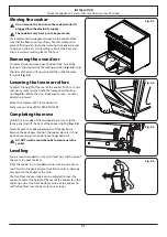
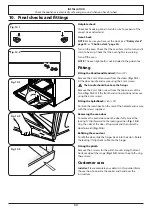
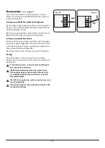
Removing the oven door

To remove the oven door, open the door fully. Swivel the 

locking ‘U’ clips forward to the locking position (

Fig. 9.3

). Grip 

the sides of the door, lift upwards and then slide the door 

forwards (

Fig. 9.4

).

Lowering the two rear rollers

To adjust the height of the rear of the cooker, first fit a 13 mm 

spanner or socket wrench onto the hexagonal adjusting 

nut (

Fig. 9.5

). Rotate the nut – clockwise to raise – counter-

clockwise to lower.
Make 10 complete (360°) turns clockwise.
Make sure you lower BOTH REAR ROLLERS. 

Completing the move

Unfold the rear edge of the cardboard base tray. Grip the 

fascia panel and lift the front of the cooker slightly (

Fig. 9.6

).

Carefully push the cooker backwards off the pack base. 

Remove the pack base. Position the cooker close to its final 

position, leaving just enough space to get behind it.


n

DO NOT use the control knobs to manoeuvre the 

cooker.

Levelling

You are recommended to use a spirit level on a shelf in one of 

the ovens to check for level.
Place the cooker in its intended position, taking care not to 

twist it within the gap between the kitchen units as damage 

may occur to the cooker or the units.
The front feet and rear rollers can be adjusted to level the 

cooker. To adjust the height of the rear of the cooker turn the 

adjusting nuts at the front bottom corners of the cooker. To 

set the front feet turn the bases to raise or lower.

Fig. 9.3


Fig. 9.4


Fig. 9.5


Fig. 9.6


Summary of Contents for Classic FX 90 Induction

Page 1: ...USER GUIDE INSTALLATION INSTRUCTIONS Classic FX 90 Induction Professional FX 90 Induction Australia 08 000005 01...

Page 2: ......

Page 3: ...n 15 Energy Saving Panel 16 Accessories 17 3 Rotary clock 18 4 3 button clock 20 5 Cooking tips 22 6 Cooking table 23 7 Cleaning your cooker 24 8 Troubleshooting 27 9 Installation 29 Safety requiremen...

Page 4: ...ii...

Page 5: ...cooker should not be placed on a base This appliance is designed for domestic cooking only Use for any other purpose could invalidate any warranty or liability claim Before operating the oven s pleas...

Page 6: ...l supply type Fig 1 1 and Fig 1 2 Check that the links are correctly fitted and that the terminal screws are tight Secure the mains cable using the cable clamp Minimum temperature rating T105 Read the...

Page 7: ...ll a powered cookerhood that vents outside If you have several hotplates burners on or use the cooker for a long time open a window or turn on an extractor fan Maintenance Only a qualified service eng...

Page 8: ...e sides of the pan Carefully watch for spills or overheating of foods when frying at high or medium high temperatures DO NOT use the top of the flue the slot along the back of the cooker for warming p...

Page 9: ...l enamelled steel pans or cast iron pans with enamelled bases are suitable for induction hob cooking Take care NOT to scratch the surface when placing cookware on the glass panel Only certain types of...

Page 10: ...t ideal to provide best performance and can result in premature component failure Oven care When the oven is not in use and before attempting to clean the cooker always be certain that the control kno...

Page 11: ...o the OFF position before removing a pan Avoid heating an empty pan Doing so may damage both the hob and pan Cooling fan This appliance may have a cooling fan When the grill or oven is in operation th...

Page 12: ...r NEVER use caustic or abrasive cleaners as these will damage the surface DO NOT use steel wool oven cleaning pads or any other materials that will scratch the surface NEVER store flammable materials...

Page 13: ...on cooker has the following features A 5 induction cooking zones B A control panel C A multi function oven D A storage drawer 2 Overview ArtNo 273 0003 90IN Prof annotated Professional FX A B C D Fig...

Page 14: ...rning onto the hob panel This also helps prevent scratches and deposits Always use pans that are the same size as or slightly larger than the areas marked on the hob Using a lid will help the contents...

Page 15: ...H will go out Automatic Heat up A This function is available on all of the cooking zones It allows rapid heating up of the element to bring the selected cooking zone up to temperature Once the zone is...

Page 16: ...tomatically If required you can immediately restart the Low Temperature function by reactivating L1 or L2 Power Boost Setting P All of the induction cooking zones have Power Boost available activated...

Page 17: ...carefully before using cookware on your induction hob Multifunction Oven The oven is a multi function oven Fig 2 10 As well as the oven fan and fan element they are fitted with two extra heating eleme...

Page 18: ...he grill pan tray support on the second from top level Fan Assisted Oven D This function operates the fans circulating air heated by the elements at the top and the base of the oven The combination of...

Page 19: ...oven lights fail turn off the range circuit breaker before you change the bulb See the Troubleshooting section for details on how to change an oven light bulb Fig 2 16 ArtNo 320 0017 Main oven light...

Page 20: ...he left hand side as well as those on the right when a function is selected All oven functions are available in full and divided forms and shelves are provided for use in both forms n WARNING Take gre...

Page 21: ...lves Pull the shelf forwards until the back of the shelf is stopped by the shelf support Fig 2 20 Lift up the front of the shelf so the back of the shelf will pass between the supports and then pull t...

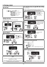
Page 22: ...e The cook symbol remains visible during normal operation OR The clock must be set to the time of day before the oven will work Alarm will sound when cooking has finished to cancel follow this step ma...

Page 23: ...set the time of day you want the oven to stop cooking Current time will be displayed along with the word AUTO Set the oven to the required cooking temperature and function Set the cook time Alarm will...

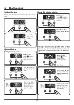
Page 24: ...Note The cook symbol remains visible during normal operation Press either the or buttons Press either the or buttons to set the timer Once the specified time has elapsed an alarm will sound To stop t...

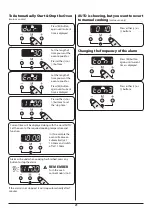
Page 25: ...e and function ArtNo 306 0001 3 button clock Alarm will sound when cooking has finished press any button to stop the alarm If the alarm is not stopped it will stop automatically after 7 minutes Set th...

Page 26: ...th a multifunction oven Remember not all modes are suitable for all food types The oven cooking times given are intended for a guide only General oven tips The wire shelves should always be pushed fir...

Page 27: ...e 2 2 hours Up to 3 hours 80 90 minutes 15 25 minutes 10 15 minutes 20 30 minutes 30 40 minutes 20 30 minutes on a preheated tray 35 45 minutes 10 20 minutes according to size 20 40 minutes according...

Page 28: ...the hot zone with a clean paper towel If a spill other than a sugary substance is on the hot zone do not clean until the unit has completely cooled down and then follow the instructions below Cleaning...

Page 29: ...t no surplus water seeps into the appliance Wipe with a clean dampened cloth then polish with a dry cloth The oven doors should only be cleaned with a soft cloth wrung out in clean hot soapy water Rem...

Page 30: ...eam cleaner with care if necessary Control panel Paint enamel or stainless steel Warm soapy water Do not use abrasive cleaners on lettering Control knobs handles trims Plastic chrome copper or lacquer...

Page 31: ...e some noise emitted from the pan This is normal and may be most noticeable when cooking on high power settings or if 5 pans are used simultaneously The type of pan may also contribute to induction no...

Page 32: ...nly Do not use a baking tray with dimensions larger than those specified in the section on General Oven Tips If you are cooking a large item be prepared to turn it round during cooking If two shelves...

Page 33: ...vice Therefore particular attention must be given to the relevant requirements regarding ventilation All rooms require a window that can be opened or equivalent while some rooms require a permanent ve...

Page 34: ...facturers instructions Allowance should be made for the additional height of the flue trim which is fitted to the cooker hob Surfaces of furniture and walls at the sides and rear of the appliance shou...

Page 35: ...nal adjusting nut Fig 9 5 Rotate the nut clockwise to raise counter clockwise to lower Make 10 complete 360 turns clockwise Make sure you lower BOTH REAR ROLLERS Completing the move Unfold the rear ed...

Page 36: ...as short as is practicable and fixed firmly to the rear of the cooker If you are using a stability bracket Fig 9 8 and Fig 9 9 then adjust the bracket to give the smallest practicable clearance betwe...

Page 37: ...the terminal screws are tight Secure the mains cable using the cable clamp Repositioning the cooker following connection If you need to move the cooker once it has been connected make sure it is isola...

Page 38: ...it the front handrail in position and secure using the 4 mm screws Fitting the Splashback Classic FX Position the splashback on the rear of the hotplate and secure with the screws supplied Removing th...

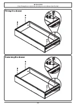
Page 39: ...INSTALLATION Check the appliance is electrically safe and gas sound when you have finished 35 Removing the drawer Fitting the drawer...

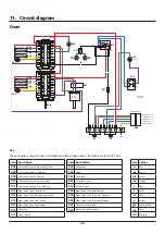
Page 40: ...7 X14 Code Description X06 Left Hand Oven Multifunction Switch X08 Left Hand Oven Base Element X09 Left Hand Oven Fan Element X10 Left Hand Oven Top Outer Element X11 Left Hand Oven Top Inner Element...

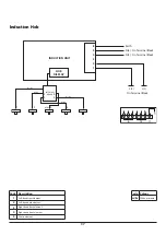
Page 41: ...rth N 6 N 4 L 2 L 3 On Terminal Block On Terminal Block On Terminal Block w br w br w br w br w br Induction Hob Code Description 1 Left hand front element 2 Left hand back element 3 Right hand back e...

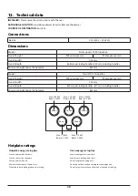
Page 42: ...th 900 mm Overall depth 607 mm excluding handles 671 mm including handles Minimum height above the hotplate 650mm Hotplate ratings Hotplate energy saving tips Oven energy saving tips Use cookware with...

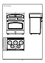
Page 43: ...39 900 608 DEPTH EXCLUDING HANDLES 642 DEPTH INCLUDING HANDLES 608 DEPTH EXCLUDING HANDLES 642 DEPTH INCLUDING HANDLES Professional FX Induction...

Page 44: ...40 607 DEPTH EXCLUDING HANDLES 671 DEPTH INCLUDING HANDLES 900 607 DEPTH EXCLUDING HANDLES 671 DEPTH INCLUDING HANDLES Classic FX 90 Induction...

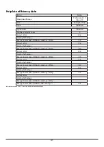
Page 45: ...echnology Energy Consumption ECElectric cooking Wh kg 180 Zone 3 cm 18 5 Heating Technology Energy Consumption ECElectric cooking Wh kg 172 Zone 4 cm 15 5 Heating Technology Energy Consumption ECElect...

Page 46: ...gy consumption electricity conventional kWh cycle 1 16 Energy consumption electricity forced air convection kWh cycle 1 03 Energy efficiency index conventional 112 8 Energy efficiency index forced air...

Page 47: ......

Page 48: ...Clarence Street Royal Leamington Spa Warwickshire CV31 2AD England www falconworld com...

Reviews: